The SmartView Visual Communication System, manufactured by RATH® and JANUS, is an emergency communication solution designed for elevators. This system integrates visual and audio communication, allowing for remote assistance and monitoring. RATH® is a prominent manufacturer in North America, with over 35 years of experience in emergency communication products.
Function Description:
The SmartView system provides a visual communication link between an elevator car and a remote monitoring station, often referred to as a "Head-End Controller." It enables two-way visual and text-based communication, allowing occupants to see and be seen by rescue services, and to respond to prompts via "YES" and "NO" buttons. This is particularly useful in situations where verbal communication might be difficult or impossible, or where visual confirmation of an occupant's status is critical. The system is designed to operate reliably, even if the external internet connection is compromised, by wiring the Head-End and Controllers back to the same network switch.
Key Components:
- SmartView Controller: The central processing unit within the elevator car. It manages the camera, display, and button inputs, and facilitates communication with the remote monitoring station.
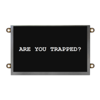
- SmartView Display (or CE Elite PI Display): A screen mounted in the elevator panel that shows messages from rescue services and the camera feed.
- SmartView Camera: Captures video from inside the elevator car, transmitting it to the remote monitoring station.
- YES/NO or DOOR OPEN/DOOR CLOSE Buttons: Allow occupants to respond to prompts from rescue services.
- Ethernet Extenders (2100-SVE): Used for long-distance power and data transmission over a single pair of wires, extending communication up to 1,640 feet.
- Head-End Controller: The remote monitoring station where rescue services can view camera feeds, send messages, and manage multiple SmartView devices.
Important Technical Specifications:
SmartView Controller:
- Power Requirements: 12V or 24V DC, or Power over Ethernet (PoE/PoE+).
- Current Draw:
- 12V Active: 1A
- 12V Idle: 0.5A
- 24V Active: 0.5A
- 24V Idle: 0.25A
- Operating Temperature: 32°F to 158°F (0°C to 70°C).
- Dimensions: 4" H x 7" W x 1.2" D.
- Internet Requirements: Routed internet connection using DHCP or a wireless data device (cellular modem with data) provided by RATH®.
- Connectivity: USB for camera, HDMI for display, Ethernet for network.
SmartView Camera:
- Power Requirements (Powered by Controller):
- Active: 5V, 0.12A
- Idle: 0V, 0A
- Operating Temperature: 32°F to 140°F (0°C to 60°C).
- Distance from Controller: Must be no more than 15 feet.
SmartView Display:
- Power Requirements (Powered by Controller):
- Active: 5V, 0.59A
- Idle: 0V, 0A
- Operating Temperature: -4°F to 158°F (-20°C to 70°C).
- Screen Size: 5 inches.
- Part Numbers (with window thickness options):
- 2100-SVD (0.0625" window)
- 2100-SVDA (0.125" window)
- 2100-SVDB (0.109" window)
- 2100-SVDC (0.078" window)
- 2100-SVDE (0.118" window)
- Distance from Controller: Must be no more than 20 feet.
Ethernet Extenders (2100-SVE):
- Power: Supplies 1A to the SmartView Controller.
- Wiring: Extends up to 1,640 feet over a single pair of 18-24AWG shielded or unshielded wire.
- Connectivity: CAT5E with RJ45 connectors for network switch and SmartView Controller.
- Main Unit (Injector): LAN In (internet connection) and LRP Out (two-wire connection).
- Remote Unit (Extender): LRP In (two-wire connection from main unit) and PoE Out (Ethernet connection to SmartView Controller).
Usage Features:
- Remote Monitoring: Rescue services can view live camera feeds from the elevator car.
- Two-Way Text Communication: Messages can be sent from the Head-End to the SmartView Display, and occupants can respond using "YES" or "NO" buttons.
- Easy Setup: The system uses a flash drive with a SmartView link for initial setup and testing.
- Multiple Power Options: Supports 12V/24V direct power, PoE+, or 2100-SVE Ethernet Extenders, offering flexibility for various installation environments. Crucially, only one power source should be used at a time.
- In-Building Intercom Master Setup: The Head-End Controller can link multiple SmartView devices, displaying their IDs and providing a view icon for each.
- LAN Setup: Designed to maintain operation even if the external internet is compromised, by ensuring Head-End and Controllers are wired to the same local network switch.
Maintenance Features:
- Troubleshooting Guide: The manual provides a comprehensive troubleshooting section for common issues such as a blank display, device offline status, connection problems, invalid SmartView ID, and flickering Ethernet lights.
- Customer Support: RATH® offers experienced customer support teams available for remote assistance with site preparation, installation, and maintenance.
- Diagnostic Tools: Holding the "YES" and "NO" buttons simultaneously for 7 seconds will display the device's IP address and server connection on the display, aiding in diagnostics.
- Visual Verification: The system allows for visual verification of network connectivity through amber and flashing green lights on the Ethernet port of the Controller.
- 3-Year Warranty: The product comes with a 3-year warranty, indicating manufacturer confidence in its durability and reliability.
The SmartView Visual Communication System is a robust and user-friendly solution designed to enhance safety and communication in elevator emergencies, providing peace of mind for both occupants and rescue personnel.