Installation & Operating Manual /DISC-O-FLEX/RLM,RLMK
RATHI TRANSPOWER PVT.LTD. Gaia Apex,S No 33/2D,Viman Nagar R-II-D-03/02-09/20
Pune, 411014 Page 6 of 15
GO TO INDEX
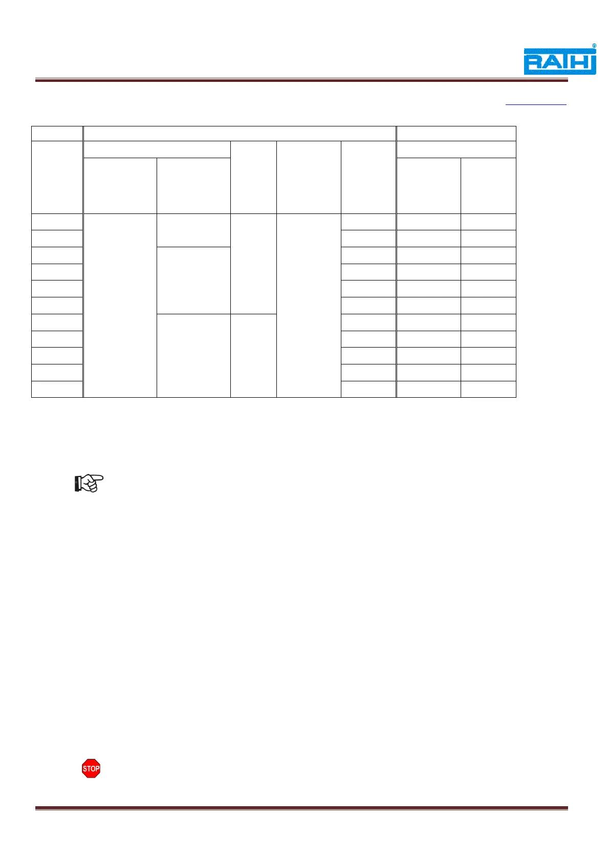
Table 3 : Misalignment & Tightening Torque
Gap ‘G’ in above table is given when angular and axial misalignments are zero.
# SPAN = DBSE – G
For RLMK Couplings, parallel misalignment is zero.
3.4 Final Assembly
RLM/RLMK couplings are supplied with fully assembled condition with tightened
cleveloc nuts(7) at RTPL to specified tightening torque (Table 3).
Ensure hubs have been mounted as shown in fig.4,to maintain correct DBSE .
3.4.1 RLM
Support the center spacer between two hubs and ensure small holes of spacer flange
will be in line with the large holes of the hub.
Insert Allen head bolts with sleeves from hub side, first through the large holes and
then small holes by holding blade pack assembly between hubs & center spacer.
3.4.2 RLMK
The large holes of Hub-II should be in line with the small holes of Hub-I
Insert coupling bolts from driven hub side through small hole and small length sleeves
from driving side.
Insert coupling bolts with long sleeves through the large holes of driven hub
To avoid loosening of nut, apply thread locker, loctite 270 solution on threads before
tightening the bolts
Tighten the cleveoc nut with to the required tightening torques given in table 3.
Follow the same procedure from other side also for RLM.
Measure gap ‘G’ mentioned in table 2 , which should be equal throughout on both sides.
Customer must provide required safety guards, RTPL does not supply safety guards or
shields.