Do you have a question about the Rational SCC WE 61E and is the answer not in the manual?
General warnings about installation, service, maintenance, and usage of the unit.
Safety instructions for gas units regarding waste gases and fire hazard.
Safety measures in case of gas smell to prevent explosion hazards.
Precautions for storing flammable vapors or liquids near the appliance.
Explains the danger symbol indicating a situation that can cause severe injury or death.
Explains the warning symbol indicating a situation that can cause severe injury or death.
Explains the fire hazard symbol.
Explains the danger of burning symbol.
Explains the high voltage danger symbol indicating a life-threatening situation.
Warning about the risk of scalding when using containers with liquids at high levels.
Procedure for changing the air filter, differentiating between operator and qualified personnel tasks.
Description of the automatic self-test process for new unit commissioning and its duration.
Instructions for placing GN containers correctly for the self-test based on unit size.
Cautionary note about fire hazards related to packing material and interior cabinet contents during commissioning.
Warning about the risk of unit tilting during transport and how to secure it.
Advice on observing unit weight, using carrying aids, and wearing safety boots.
Specifies minimum clearances for left, right, and rear sides for non-floor models.
Specifies minimum left-side clearance for 20x1/1 and 20x2/1 GN floor models for power cable installation.
Defines minimum clearance when heat sources are present on the left-hand side.
Prohibits installation of deep fat fryers near the unit and specifies frost-free room installation.
Requirements for exhaust air routing, including space for condensation breakers.
Emphasizes installing table units on original manufacturer stands for safety reasons.
Specific instructions for installing gas units on tables or floors, including pedestal and plate fitting.
Instructions for fixing gas appliance stands to the floor using a specified fixing set.
Instructions for additionally securing units mounted on mobile stands to prevent slipping and damage.
Procedure for fixing floor locks using screws, pins, or adhesive.
Warning about scalding risk from hot liquids if floor incline exceeds 4°.
Alert that incorrect trolley leveling can cause unit malfunction, e.g., during Cleanjet.
Warning about avoiding steam sources near the air filter to prevent damage and malfunction.
Warning about high voltage, danger to life, and the importance of local regulations.
Details on electrical units requiring independent fused power supply and permanent connection.
Specifications for gas units, including power cable details and plug types.
Critical warning about observing mains polarity for gas units to ensure burner function.
Instructions for connecting the earth bonding wire to the designated stud on the unit.
Warnings about electric shock, danger to life, and wire color coding during electrical connections.
Alert that incorrect electrical connections can lead to unit damages, such as to the fan motor.
Procedure for converting 208V units to 240V, including switch and transformer adjustments.
Procedure for converting 480V units to 440V, involving adapter cables and switch settings.
General advice on checking connections, following instructions, and complying with codes.
Details on using NEC UL standard cords and specific supply requirements.
Details on power cable exchange for gas units and compliance with local standards.
Specifies drinking water quality and a maximum recommended water temperature of 86°F.
Requirement for adequate back-flow protection to comply with plumbing codes.
Requirement for facility water supply hoses to conform to EN/IEC 61770 or similar quality.
Ensures water supply hoses meet local and hygiene requirements for drinking water systems.
Prohibits reuse of old supply hoses; only new hoses are permitted.
Specifies the required connected water pressure range and the recommended pressure.
General advice on water treatment, especially for water hardness below 5 gr/gal.
Warning against supplying water with hardness less than 5 gr/gal due to corrosive properties.
Guidance for setting water hardness levels on 5Senses models during self-test.
Suggests consulting local water providers for advice on filters (A, B, C, D) based on water conditions.
Recommendation for de-ionization systems if chloride concentration exceeds 4.68 gr/gal to prevent corrosion.
Requirement to analyze exhaust gases (CO, CO2) during commissioning for accurate burner settings.
Warnings about fire hazard, danger to life, and the need to observe local regulations for gas connections.
Mandates compliance with local gas authority regulations and installation instructions.
Instruction to verify that the supplied gas type is compatible with the unit.
Requirement for gas pipe diameter to comply with local regulations.
Mandates checking the gas supply and internal lines for leakage.
Stipulates connection by a locally approved gas installer and matching pipe widths for meters.
Instructions for handling flow pressure deviations and disconnecting supply if natural gas pressure exceeds limits.
Warning about suffocation hazard from gaseous combustion products (CO, CO2).
Mandates well-ventilated rooms to prevent hazardous combustion product buildup.
Requires gas units to be placed under an externally vented exhaust hood according to local regulations.
Specifies installation conformity requirements with CGA-B 149.1 (natural gas) and CGA-B 149.2 (propane) codes.
Details gas consumption (gross calorific value) for various unit sizes and gas types at nominal heat load.
Emphasizes using pipes capable of withstanding steam temperature and avoiding hoses.
Specifies using a 2" (50 mm) pipe with a constant gradient (min. 5% or 3°) and not reducing its diameter.
Details ventilation requirements for gas and electric units based on cooking and local jurisdiction.
Emphasizes compliance with local regulations and standards like NFPA 96 for ventilation.
Warns about suffocation hazards from flue gases (CO, CO2) and the need for ventilation.
Provides power kW and running amps for electric SCC_WE, CM_P units in USA/Canada.
Provides electrical connection power kW and running amps for gas SCC_WE, CM_P units in USA/Canada.
Provides power kW and electricity consumption (Amps) for electric SCC_WE, CM_P units in Europe.
Provides power kW and electricity consumption (Amps) for gas SCC_WE, CM_P units in Europe.
Identifies the gas supply connection point (3/4") for 6x1/1 GN Gas units.
Identifies the gas supply connection point (3/4") for 6x2/1 GN Gas units.
Identifies the gas supply connection point (3/4") for 10x1/1 GN Gas units.
Identifies the gas supply connection point (3/4") for 10x2/1 GN Gas units.
Identifies the gas supply connection point (3/4") for 20x1/1 GN Gas units.
Identifies the gas supply connection point (3/4") for 20x2/1 GN Gas units.
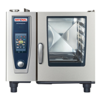
| Model | SCC WE 61E |
|---|---|
| Type | Combi Oven |
| Capacity | 6 x 1/1 GN |
| Width | 847 mm |
| Height | 782 mm |
| Electrical connection | 3 NAC 400 V |
| Cooking modes | Steam, Convection, Combination |
| Control | Touchscreen |
| Power Supply | Electric |
| Temperature Range | 30°C - 300°C |