INSTRUCTION, USE AND
MAINTENANCE MANUAL
GB
Page 14 of 60
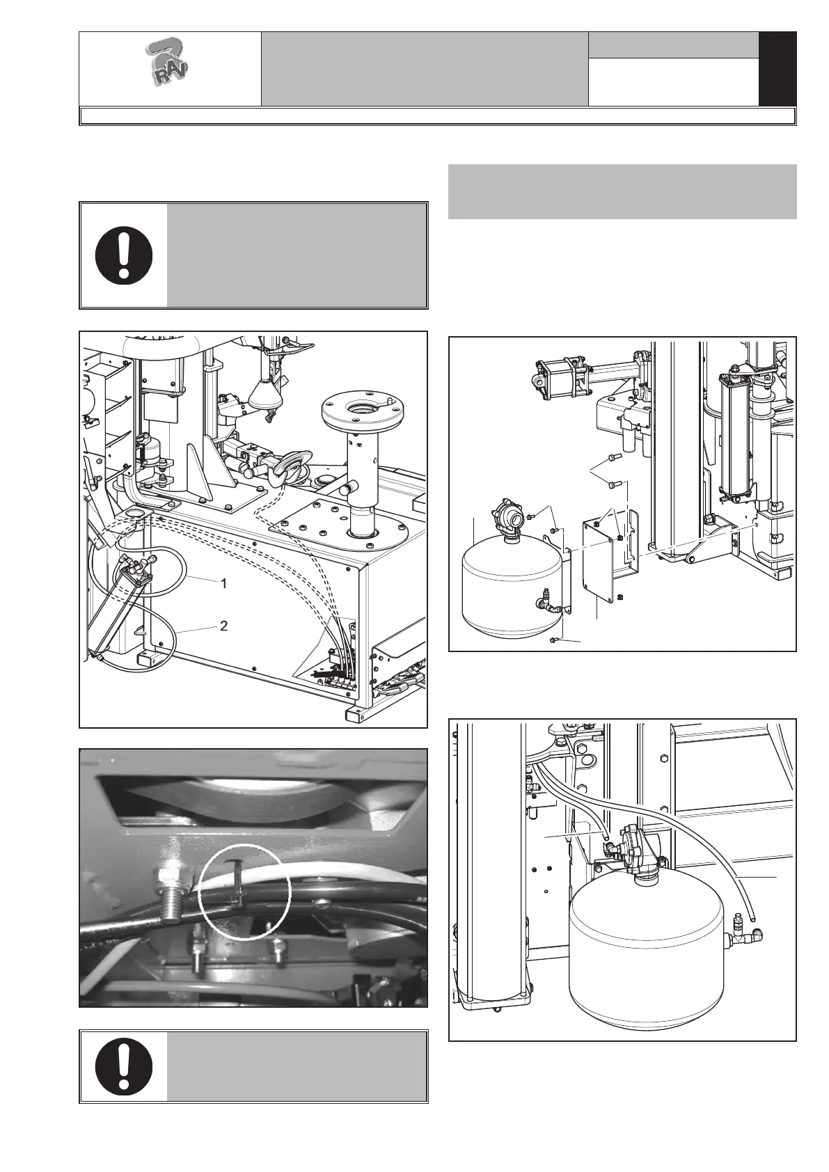
6. Fix the pneumatic pipes (Fig. 8 ref. 1-2) coming from
the lifting device pedalboard to the lifting cylinder,
as shown in Fig. 8.
BEFORE CONNECTING THE PIPES
(FIG. 8 REF. 1-2), MAKE SURE
THEY PASS THROUGH THE RUB-
BER FAIRLEAD PLACED ON THE
MACHINE BASE AND THE LIFTING
DEVICE FRAME.
Fig. 8
Fig. 9
FASTEN THE PIPES AS SHOWN
IN FIG. 9 IN ORDER TO AVOID
THAT THEY INTERFERE WITH
THE BELT.
RAVAGLIOLI S.p.A.
7300-M018-2_R
G8945.26 - G8945IT.26 - G8945V.26 - G8945ITV.26 - G8945V.26S - G8945ITV.26S - G8945D.26 - G8945ITD.26 - G8945D.26S - G8945ITD.26S
Tubeless inflation tank installation
Only for G8945IT.26 - G8945ITV.26 -
G8945ITV.26S - G8945ITD.26 - G8945ITD.26S
models
7. Fix the bracket (Fig. 10 ref. 1) (# 730022630) with
the two screws (Fig. 10 ref. 2) (# 203193).
Fix the tank (Fig. 10 ref. 3) to the bracket (Fig.
10 ref. 1) using the 4 screws (Fig. 10 ref. 4) (#
272019) and the 4 crated nuts (Fig. 10 ref. 5) (#
228206) on issue.
1
2
3
4
4
5
Fig. 10
8. Connect the black pipe (Fig. 11 ref. 1) and the blue
pipe (Fig. 11 ref. 2) on the provided quick couplings
as shown in Fig. 11.
1
2
Fig. 11
 Loading...