INSTRUCTION, USE AND
MAINTENANCE MANUAL
GB
Page 15 of 60
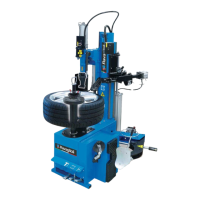
12. Connect the main pneumatic supply (Fig. 14
ref. 1) by linking connection on the machine filter
unit.
The pressurized pipe coming from the mains must
have a section of 10x19 (see Fig. 14).
Fig. 14
13. Reassemble the lateral carter (Fig. 6 ref. 1)
that was unscrewed before.
IF OTHER PNEUMATIC CONNEC-
TIONS SHOULD BE EXECUED,
REFER TO THE PNEUMATIC DIA-
GRAMS ILLUSTRATED IN CHAPT.
19.
RAVAGLIOLI S.p.A.
7300-M018-2_R
G8945.26 - G8945IT.26 - G8945V.26 - G8945ITV.26 - G8945V.26S - G8945ITV.26S - G8945D.26 - G8945ITD.26 - G8945D.26S - G8945ITD.26S
Installation of Plus device
Only for G8945V.26S - G8945ITV.26S -
G8945D.26S - G8945ITD.26S models
9. Mount the Plus device (Fig. 12 ref. 1) with the
screws (# 203074) (Fig. 12 ref. 2), the washers (#
237025) (Fig. 12 ref. 3) and the nuts (# 228014)
(Fig. 12 ref. 4) on issue.
1
2
2
3
3
3
4
4
Fig. 12
10. Connect the main pneumatic supply to Plus device.
Installation of tool box, pneumatic connection and
bead breaker vane
Valid for all the models
11. Mount the tool box (Fig. 13 ref. 1) using the
screws (# 203193) (Fig. 13 ref. 2) and the nuts
(# 228012) (Fig. 13 ref. 3).
Fig. 13
 Loading...