4
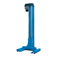
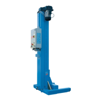
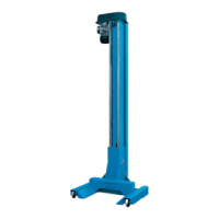
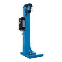
RAV261-2-L RAV263-4-L RAV265-6-L
0523-M002-3
INDICE
I
CONTENTS
0. ALLGEMEINE
SICHERHEITSVORSCHRIFTEN
0.1 Hinweise zu den Restrisiken
1. SICHERHEITSEINRICHTUNGEN
1.1 Verriegelbarer Hauptschalter
1.2 Totmann-System
1.3 Mechanische Not-Aus-Vorrichtung
1.4 Gleichlaufregelung der Hubwagen
1.5 Not-Aus
1.6 Bei Not-Aus zugelassene Bewegungen
1.7 Abschaltung bei Tragmutterabnutzung
1.8 Abschaltung bei Hindernis
1.9 Auf der Hebebühne vorhandene
Gefahrenzeichen
2. BESTIMMUNGSGEMÄSSE
VERWENDUNG
3. TECHNISCHE DATEN
3.1. Transport und Installationsvorbereitung
4. BESCHREIBUNG DER HEBEBÜHNE
4.1 Technische Haupteigenschaften
4.2 Betriebstüchtigkeit
5.KONTROLLE DER
MINDESTANFORDERUNGEN AN DEN
AUFSTELLUNGSORT
6. GEBRAUCHSANLEITUNG
6.1 Installationsanforderungen
6.2 Kontrolle der Spannung
6.3 Netzanschluss
6.3.1 Aktivierung des Schaltschrankes
6.4 Umwandlung der Hebebühne mit 6/8 Säulen
6.5 PLC-Konfiguration
6.6 Umwandlung von 6/8 auf 4 Säulen
6.7 Kabelanschluss
6.8 Anschluss der Verbindungskabel
7. ANWEISUNGEN FÜR DIE BEDIENUNG DER
HEBEBÜHNE
7.1 Unsachgemäße Bedienung der Hebebühne
7.2 Gebrauch von Zubehörteilen
7.3 Schulung des Bedienungspersonals
7.4 Vorsichtsmaßnahmen
7.5 Steuerungen und deren Funktionen
7.6 Komplettierung und Kontrolle
7.7 Demontage
7.8 Positionieren für das Heben von
Fahrzeugen
7.9 Gleichzeitiger Betrieb mit versetzten Säulen-
Paaren
7.10 Einzel-Betrieb
7.11 Stützsäulen (optional)
7.12 Not-Aus-Verfahren: Senken bei Not-Aus
oder bei Stromausfall
7.12.1 Not-Aus (einzeln)
7.12.2 Absenken ohne Strom
8. BETRIEBSSTÖRUNGEN
8.1 Verzeichnis der Signallampen
9. INSTANDHALTUNG
9.1 Gleitbahnen
9.2 Schmierbehälter
9.3 Tragmuttern
9.5 Reinigung und Betriebskontrollen der
Sicherheitsvorrichtunger
10. EINLAGERUNG
10.1 Verschrottung
11 ELEKTROANLAGE
11.1 Elektrischen Anlage - zusatzschalttafel
11.2 Elektrischen Anlage -hauptschalttafel
- ERSATZTEILELISTEN
INHALTSVERZEICHNIS
0. NORME GENERALI Dl SICUREZZA
0.1 Indicazioni dei rischi residui
1. DISPOSITIVI Dl SICUREZZA
1.1 Interruttore generale lucchettabile
1.2 Sistema a uomo presente
1.3 Blocco meccanico demergenza
1.4 Riallineamento automatico carrelli
1.5 Blocco di emergenza
1.6 Manovre permesse in condizioni di
blocco emergenza
1.7 Arresto usura chiocciole
1.8 Arresto per ostacolo
1.9 Pittogrammi presenti sul sollevatore
2. DESTINAZIONE DUSO
3. DATI TECNICI
3.1 Movimentazione e preinstallazione
4. DESCRIZIONE DEL SOLLEVATORE
4.1 Caratteristiche tecniche principali
4.2 Attitudine allimpiego
5. VERIFICA DEI REQUISITI MINIMI
RICHIESTI PER LUOGO Dl INSTALLAZIONE
6. ISTRUZIONI PER LUSO
6.1 Requisiti per linstallazione
6.2 Controllo tensione elettrica
6.3 Allacciamento alla rete elettrica
6.3.1 Attivazione quadro elettrico
6.4 Trasformazione 6/8 colonne
6.5 Configurazione PLC
6.6 Trasformazione da 6/8 colonne a 4 colonne
6.7 Allacciamento cavi
6.8 Allacciamento cavo di interconnessione
7. ISTRUZIONI PER LUSO DEL
SOLLEVATORE
7.1 Uso improprio del sollevatore
7.2 Uso di accessori
7.3 Addestramento del personale preposto
7.4 Precauzioni duso
7.5 Identificazione dei comandi e loro funzione
7.6 Completamento e controllo
7.7 Smontaggio
7.8 Posizionamento per il sollevamento
autoveicolo
7.9 Funzionamento simultaneo con coppie di
colonne sfalsate
7.10 Funzionamento singolo
7.11 Colonnette di supporto (optional)
7.12 Procedure di emergenza :discesa di
emergenza o in assenza di tensione elettrica
7.12.1 Discesa di emergenza (in singolo)
7.12.2 Discesa in assenza di tensione
8. INCONVENIENTI
8.1 Elenco segnalazioni
9. MANUTENZIONE
9.1 Guide di scorrimento
9.2 Vaschette di lubrificazione
9.3 Chiocciole portanti
9.4 Cuscinetti
9.5 Pulizia e verifiche funzionamento
dispositivi di sicurezza
10. ACCANTONAMENTO
10.1 Rottamazione
11. IMPIANTO ELETTRICO
11.1 Impianto elettrico quadro secondario
11.2 Impianto elettrico quadro principale
- TAVOLE PEZZI DI RICAMBIO
0. GENERAL SAFETY PRECAUTIONS
0.1 Indications of outstanding risks
1. SAFETY DEVICES
1.1Padlockable main switch
1.2 Deadman device
1.3 Mechanical emergency stop
1.4 Automatic carriage height
synchronisation
1.5 Emergency block
1.6 Manoeuvres permitted in emergency
block conditions
1.7 Nut wear stop
1.8 Obstacle stop
1.9 Pictograms on lift
2. INTENDED USE
3. TECHNICAL DETAILS
3.1 Pre-installation and movement
4. DESCRIPTION OF LIFT
4.1 Main technical specifications
4.2 Suitability to use
5. CHECKING THE MINIMUM REQUIREMENTS
FOR THE PLACE OF INSTALLATION
6. INSTRUCTIONS FOR USE
6.1 Installation requirements
6.2 Voltage check
6.3 Connecting up to the mains
6.3.1 Electric box activation
6.4 Change to 6/8 pillars
6.5 PLC configuration
6.6 Change from 6/8 to 4 pillar lift
6.7 Cable connection
6.8 Interconnection cable
7. INSTRUCTIONS FOR USING THE LIFT
7.1 Improper use of the lift
7.2 Use of accessories
7.3 Staff training
7.4 Important checks to be made
7.5 Description and function of controls
7.6 Completion and check
7.7 Dismantling
7.8 Positioning for vehicle lifting
7.9 Simultaneous operation with staggered
column pairs
7.10 Single operation
7.11 Support posts (optional)
7.12 Emergency procedure: down
movement in case of emergency or with
power off
7.12.1 Emergency descent (in single)
7.12.2 Decent in absence of power
8. TROUBLESHOOTING
8.1 Signals list
9. MAINTENANCE
9.1 Slideways
9.2 Lubrication tanks
9.3 Main nuts
9.4 Bearings
9.5 Safety devices cleaning and operational
tests
10. STORAGE
10.1 Scrapping
11. WIRING DIAGRAM
11.1 Wiring diagram secondary board
11.2 Wiring diagram main board
- SPARE PARTS TA BLES
 Loading...


