39
RAV635.3 - 635.4 (I-SI-ISI)
RAV640.3 - 640.3.46 - 640.4 - 640.4.46 - 640.5 - 640.6 (I-SI-ISI)
RAV650.3 - 650.4 - 650.5 - 650.6 (I-SI-ISI)
0586-M050-0
P1
P2
Fig. 3
7
EV7
EV6
1
2
4
5
CP2
EV4
EV5
3
10
10
9
9
EV8
99
10 10 8 6
9
8
6
4
1
2
7
10
13
11
12
5
3
1.3 RAV640.5-640.6 ISI
RAV650.5-650.6 ISI (versioni mono centralina)
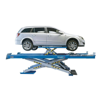
Rif. Fig. 3 - Il sollevatore viene spedito con l’impianto idraulico
nelle seguenti condizioni:
- Tubi (2-7-8-10) collegati al cilindro della pedana P1.
- Tubo (6) collegato valvola/cilindro.
- Tubi (1-4) collegati valvola/cilindro.
- Tubi (3-5) collegati ai blocchi valvole.
- Tubi (9) (pedana P2) scollegati dal blocco valvole, (le viti
cave e relative rondelle di fissaggio sono avvitate nel blocco
e protette con nastro adesivo).
- Serbatoio olio (13) vuoto.
1.3 RAV640.5-640.6 ISI
RAV650.5-650.6 ISI (single control unit versions)
Ref. Fig.3 - The lift is delivered with the hydraulic system in the
following state:
- Pipes (2-7-8-10) connected to the cylinder of the platform P1.
- Pipe (6) connected to the valve/cylinder.
- Pipes (1-4) connected to the valve/cylinder.
- Pipes (3-5) connected to the valve blocks.
- Pipes (9) (platform P2) disconnected from valve block (the
screws and retention washers are screwed into the block
and protected with adhesive tape).
- Oil tank (13) empty.
1.3 RAV640.5-640.6 ISI
RAV650.5-650.6 ISI (Versionen mit einzelner
Steuerzentrale)
Zu Abb. 3. Die Hebebühne wird mit der Hydraulikanlage in
folgendem Zustand geliefert:
- Leitungen (2-7-8-10) an den Zylinder der Fahrbahn P1
angeschlossen.
- Leitung (6) an Ventil/Zylinder angeschlossen
- Leitungen (1-4) an Ventil/Zylinder angeschlossen
- Leitungen (3-5) an die Ventilblöcke angeschlossen.
- Leitungen (9) (Fahrbahn P2) vom Ventilblock gelöst (die
Hohlschrauben und entsprechenden Befestigungsscheiben
sind im Block eingeschraubt und durch Klebeband geschützt).
- Ölbehälter (13) leer.
1.3 RAV640.5-640.6 ISI
RAV650.5-650.6 ISI (Versions avec un seul boîtier
électronique)
Réf. Fig. 3 - Au moment de la livraison du pont élévateur,
l’installation hydraulique se trouve dans les conditions
suivantes:
- Tuyaux (2-7-8-10) raccordés au vérin du chemin de
roulement P1.
- Tuyau (6) raccordé à la valve /vérin.
- Tuyaux (1-4) raccordé à la valve /vérin.
- Tuyaux (3-5) raccordés aux blocs valves.
- Tuyaux (9) (chemin de roulement P2) ne sont pas raccordés
aux blocs valves. (les vis creuses et leurs rondelles de
fixation correspondantes sont vissées dans le bloc et
1.3 RAV640.5-640.6 ISI
RAV650.5-650.6 ISI (Versiones con una sola unidad
de control)
Ref. Fig. 3 - El elevador se envía con la instalación hidráulica
en las siguientes condiciones:
- Tubos (2-7-8-10) conectados al cilindro de la plataforma P1.
- Tubo (6) conectado a válvula/cilindro.
- Tubos (1-4) conectados a válvula/cilindro.
- Tubos (3-5) conectados a los bloques válvulas.
- Tubos (9) (plataforma P2) desconectados del bloque
válvulas (los tornillos, cables y correspondientes arandelas
de sujeción están atornilladas en el bloque y protegidas con
cinta adhesiva).
P2 P1
CP1
 Loading...