Do you have a question about the Raven Viper 4 and is the answer not in the manual?
Safety precautions for electrical components during installation.
Safety precautions for hydraulic components during installation.
Important notices regarding installation and operation safety.
Guidelines for securely routing electrical harnesses to prevent damage.
Guidelines for routing flexible fluid carrying components to prevent damage.
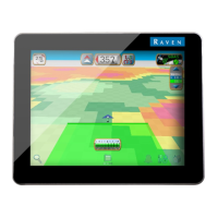
Introduction to the Viper 4 and 4+ precision agriculture management devices.
Overview of the capabilities and interface possibilities of the Viper 4 and 4+.
Raven Operating Software assists in managing implement fleets and operators.
Setting up user profiles with PINs for secure access and preferences.
Customizing screen layouts with widgets for efficient field operation.
Configuring multiple machine profiles for automatic detection and setup.
Setting up product/job info for quick selection and field work.
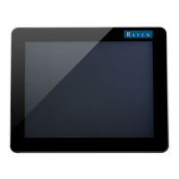
Design features for durability and heat transfer.
Transflective screen and touch screen functionality.
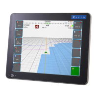
2D/3D views for equipment location and swath guidance.
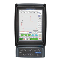
Monitoring location, recording data, and creating coverage maps.
LED indicator for device status information.
Available integrated DGPS receiver options and system integration.
Speed-compensated monitoring and automatic control for field operations.
Overview of ports and connectors for Viper 4.
Details on ports and connectors for the Viper 4+ model.
Audio jack for external sound systems or headsets.
Functionality and cautions regarding USB ports.
Connecting up to four video cameras for monitoring.
Usage of antenna ports for position information with DGPS.
Readiness for Wi-Fi connectivity and communication.
Detailed specifications for Viper 4 and Viper 4+.
Pin-out configurations for power and main interface cables.
Pin-out configurations for the auxiliary CANbus cable.
Information on the 32 GB solid-state drive for storage.
Guidelines for proper care and use to prevent damage.
Information on obtaining product software and documentation updates.
Procedures for completing the installation of a Viper 4 control system.
List of components provided with the Viper 4+ field computer kits.
Information on required cables for powering and connecting the console.
Details on optional cabling and components.
Overview of optional systems and features.
Notices regarding mounting, environmental resistance, and air gap.
Steps for securely mounting the Viper 4 or Viper 4+ field computer.
Guidelines for mounting the Viper 4 and Viper 4+ in portrait or landscape.
Recommendations for mounting DGPS antennas for optimal signal reception.
Best practices for mounting DGPS antennas for clear sky view.
Best practices for connecting the field computer, including dielectric grease and cable routing.
Steps for connecting the generation one adapter cable to the field computer.
Steps for connecting the console cable or adapter cable to the field computer.
Connecting the coaxial antenna cable to the DGPS receiver.
Instructions for connecting an external DGPS receiver.
Overview of optional connections like Wi-Fi, Ethernet, and CANbus.
Connecting the Wi-Fi antenna for future communication.
Connecting the Ethernet adapter cable for RTK corrections.
Interfacing with ISObus and J1939 networks.