5
Manual No. 016-0171-559 Rev. C 29
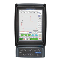
Viper® 4 and Viper 4+ System Connections
FIGURE 1. Viper 4+ Cable Connections (D/N 054-5010-010)
Antenna Cable
Viper 4/Viper 4+
*Mounting Kit Included
(Not Shown)
Aerial Antenna
Mounting Plate
MBA-6 Antenna
Camera Cable
*Viper 4 Chassis Interface or
Adapter Cable Sold Separately
Viper 4 to Viper/
Envizio Pro
Adapter Cable
To Existing
Cabling
*Kit Suffix Indicates Included Options.
Refer to Table on page 20.
Note: Refer to D/N 054-5000-001 for
other System Components
Included in “K” and “KG” Kits
Serial Extension Cable
Field Hub Power Cable
Dust Cap
Switched
Power Output
CANbus
GPS Speed
Output
GPS Receiver/
DGPS Input
Internal
GPS Output
RTK
Corrections
Remote
Switch
COM 2
Serial Console or
SmartYield Data
Switched Power
Output
Dust Cap
To Chassis or
SmarTrax Tee Cable
COM 3
Light Bar/SmartYield
Field Hub Power
Viper 4 Chassis
Interface Cable

 Loading...