RM42A Digital Stepper Drive User Manual
Page | 2
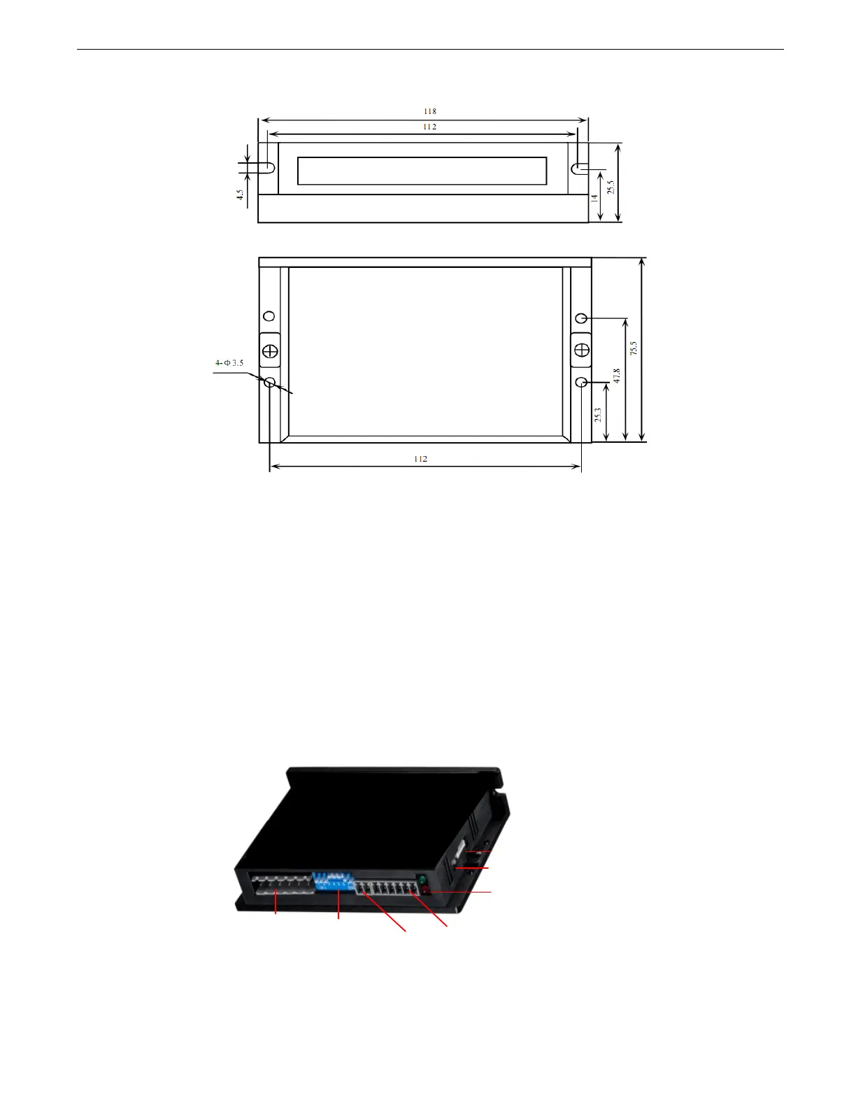
2.3 Mechanical Specifications
(unit: mm [1inch=25.4mm])
Figure 1 Mechanical specifications
• Side mounting recommended for better heat dissipation
2.4 Elimination of Heat
l RM42A reliable working temperature should be < 40
(109°F)
l It is recommended to use automatic idle-current mode to reduce motor heating. That means set the SW4 pin of DIP
switch at “OFF” position.
l It is recommended to mount the drive vertically to maximize heat sink area. Use forced cooling method to cool if
necessary.
3. Connection Pin Assignments and LED Indication
Figure 2 Connectors, DIP switches, and LED locations
The RM42A has three connector blocks P1&P2&P3 (see above picture). P1 is for control signals connections, and P2 is
for output signals connections, P3 is for power and motor connections. The following tables are brief descriptions of the
three connectors. P4 is for modifying parameters More detailed descriptions are as below.
!"#$%&'!()*+,
!-.-+*/0'"
&1#&/(-0'2'
3/*/0'4/55-+*/0
&6#789.*':9*;9*
&"#4/5*0/.'!)<58.'%5;9*=
!*8*9='>?$='
!6#4/5*0/.'!)<58.'@/.*8<-'
!-.-+*/0AB@'/0'6C@D
&C#'E95)5<'&/0*