RM42A Digital Stepper Drive User Manual
Page | 3
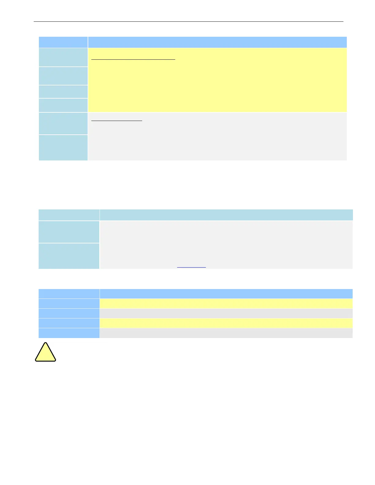
3.1 P1 - Control Connector
Pulse and Direction Connection:
(1) Optically isolated, high level 4.5-5V or 24V, low voltage 0-0.5V
(2) Maximum 200 KHz input frequency
(3) The width of PUL signal is at least 2.5μs, duty cycle is recommended 50%
(4) DIR signal requires advance PUL signal minimum 5 μs in single pulse mode
(5) The factory setting of control signal voltage is 24V, must need to set S2 (figure 2) if it is 5V
Enable Connection: (default no connection)
(1) Optically isolated, differential.
(2) Disable the drive by 4.5- 24V input connection; enable the drive by 0-0.5V connection
(3) ENA signal requires advance DIR signal minimum 5μs in single pulse mode
(4) Enable time to be at least 200ms
Notes:
(1) Shield cables are required for P1;
(2) Don’t tie P1/P2 cables and P3 cables together.
3.2 P2 - Fault Output Connector
(1) Maximum 30V/100mA output
(2) Sinking or sourcing
(3) The resistance between ALM+ and ALM- is low impedance as default, and will change to
high when the drive goes into error protection.
(4) Fault connection refer to chapter 4.2
3.3 P3 - Motor and Power Supply Connector
Power supply ground connection.
Power supply positive connection. Suggest 24-48VDC power supply voltage
Motor Phase A connections. Connect motor A+ wire to A+ Pin; motor A- wire to A-
Motor Phase B connections. Connect motor B+ wire to B+ Pin; motor B- wire to B-
Warning: Don’t plug or unplug the P1 & P2&P3 terminal block to avoid drive damage or injury when RM42A
is powered on.
3.4 P4 - RS232 Tuning Port
The P4 connector in Figure 2 is a RS232 communication port for PC connection. Refer to the following pin definitions.
It is just used to modify parameter, not for equipment control because neither precision nor stability is sufficient. If you
need a field bus drive, use a RS485 or EtherCAT type drives
The interface definition is as follows: