RM42A Digital Stepper Drive User Manual
Page | 6
6.2 Selecting Supply Voltage
The RM42A is designed to operate within 18 - 50VDC voltage input. When selecting a power supply, besides voltage
from the power supply power line voltage fluctuation and back EMF voltage generated during motor deceleration needs
also to be taken into account. Please make sure leaving enough room for power line voltage fluctuation and back-EMF
voltage charge back.
Higher supply voltage can increase motor torque at higher speeds, thus helpful for avoiding losing steps. However, higher
voltage may cause bigger motor vibration at lower speed, and it may also cause over-voltage protection or even drive
damage. Therefore, it is suggested to choose only sufficiently high supply voltage for intended applications.
7. DIP Switch Configurations
The RM42A has one 8-bit DIP switch and one 1-bit selector. The first 8-bit is used to configure settings of micro step
resolution, output current, motor standstill current, pulse type and smoothing time as shown below.
The second 1-bit selector is located on the top (S2 in figure 2), used to configure the voltage of control signals. For the
safety of optically coupled, the factory setting is 24V, which no need to connect 2K resistors like the old drives, making
it easier to use. When the voltage of the control signal is 5V, the S2 must be set to 5V, otherwise, the motor won't work.
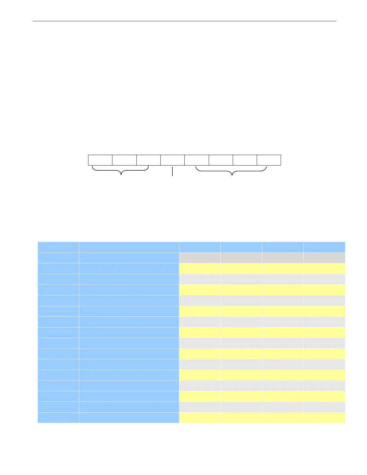
7.1 Microstep Resolution Configurations
Microstep resolution is set by SW5, 6, 7, 8 of the DIP switches as shown in the following table. Note: “default” means
the parameters can be set by software.
Steps/rev.(for 1.8°motor)