RM42A Digital Stepper Drive User Manual
Page | 4
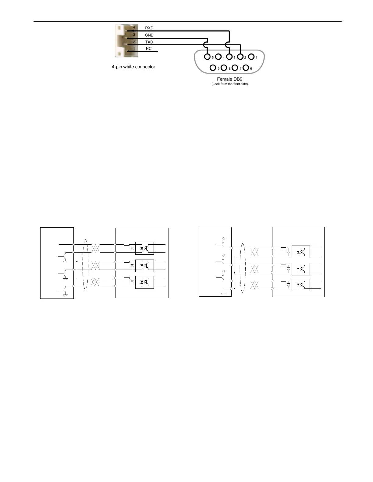
Figure 3 RS232 tuning port
3.5 LED Light Indication
There are two LED lights for RM42A. The GREEN one is the power indicator which will be always on generally. The
RED one is a protection indicator which will flash 1-2 times in a 3-second period, when protection enabled for a RM42A.
Different number of flashes indicates different protection type (read section 11 for detail).
4. Control Signal and Output Signal
4.1 Control Signal Connection
The RM42A can accept can accept differential or single-ended control signals (pulse, direction, and enable) in open-
collector or PNP connection through the P1 connector (figure 2). It is recommend to add an EMI line filter between the
power supply and the drive to increase noise immunity for the drive in interference environments.
Figure 4: Connections to open-collector signal Figure 5: Connections to PNP signal
(common-anode) (common-cathode)
Notes:
(1) ENA signal is no-connected as default;
(2) Control signal amplitude is 24 V as default. If it is 12 V, please set the S2 (Figure 2) selector switch to 5 V first, then connect
1KΩ resistor; If it is 5V, please set the S2 to 5V.
4.2 Fault Output Connection
When over voltage or over current protection happens, RM42A red status LED light will blink and the impedance state
between ALM+ and ALM- will change (from low to high or high to low depending on configuration) and can thus be
detected. Fault output connection is optional, and it can be connected either in sinking or sourcing.
Drive
Controller
VCC
PUL-
PUL+
ENA-
PUL
DIR
ENABLE
DIR-
DIR+
ENA+
Drive
Controller
VCC
PUL-
PUL+
ENA-
PUL
DIR
ENABLE
DIR-
DIR+
ENA+