User’s guide Ytterbium Pulsed Fiber Laser RFL-P10Q/P20Q/ P30Q/ P20QE/P50QB Ver.: 2.0
4 / 9
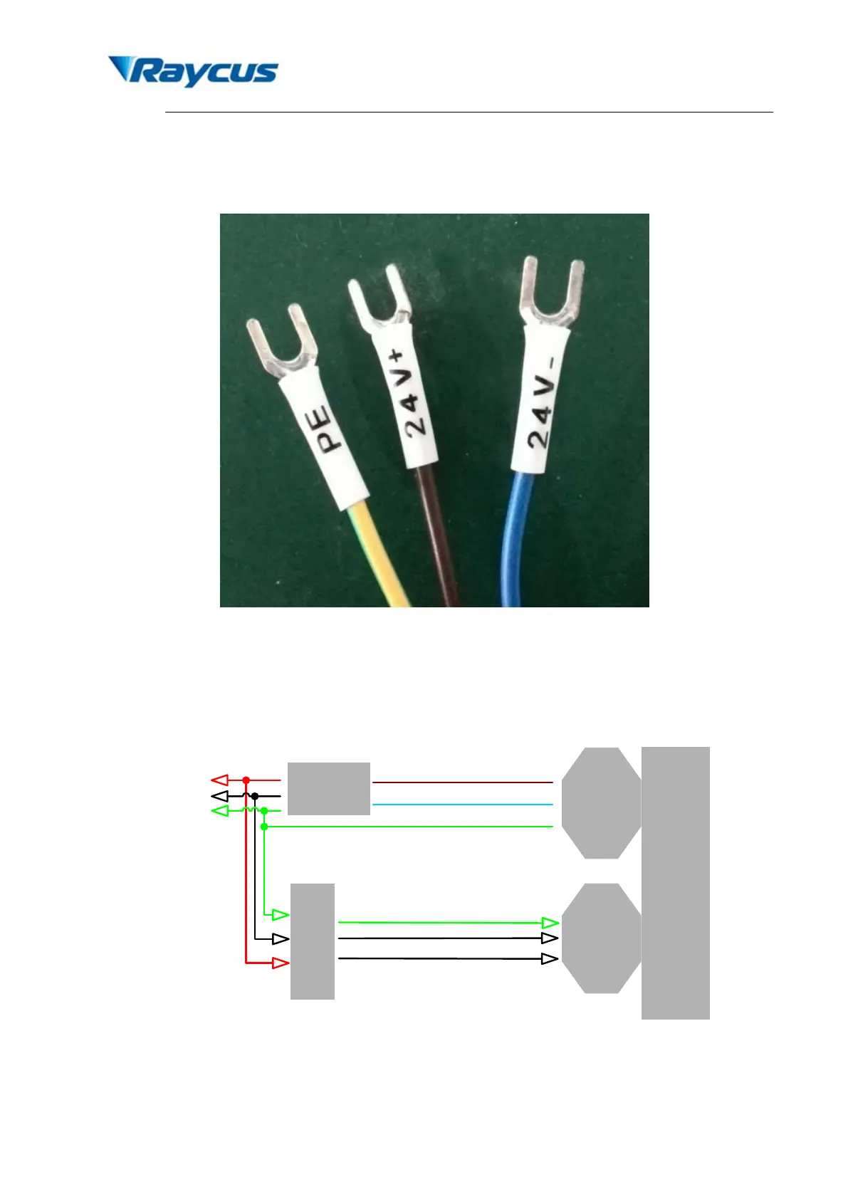
to the polarity of the electric current: anode-brown; cathode-blue; PE-yellow and green. The
definition figure is shown in Fig. 3.
Figure 3. Definition of power line wires
3) Make sure that the interface of the external controller matches the laser and the control cable
is well connected to the laser’s interface. The recommended electrical connection is shown in
Fig. 4.
User
’s
cont
rolle
r
DB25
Controller
interface
Power
supply
wire
Laser
Module
24V+(Brown)
L
N
GND
External GND
24V
power
supply
24V-(Blue)
Figure 4. Schematic of recommended electrical connection
4) The bending radius of the delivery fiber should not exceed 15 cm.