J
Justin BaileyAug 15, 2025
What improvements included the new software version of Raymarine AIS700?
- JJohn ParkerAug 15, 2025
Software version 1.09 for Raymarine Transceiver included improvements to Antenna fault detection (VSWR alarm).
What improvements included the new software version of Raymarine AIS700?
Software version 1.09 for Raymarine Transceiver included improvements to Antenna fault detection (VSWR alarm).
Why does my Raymarine AIS700 Transceiver product not turn on or keep turning off?
If your Raymarine Transceiver product doesn't turn on or keeps turning off, several factors could be at play. First, examine the fuses and breakers for any signs of damage. Replace them if necessary, ensuring the fuse rating is correct (3 A). If fuses repeatedly blow, inspect the cable for damage, broken connector pins, or incorrect wiring. Also, check the power cable connector is fully inserted and locked. Inspect the power supply cable and connectors for damage or corrosion, replacing if needed. Flex the power cable near the connector while the product is on to check for reboots or power loss, and replace the cable if this occurs. Verify the power supply voltage is a minimum of 10.2 V.
How to fix Raymarine AIS700 Transceiver that will not boot up (re-boot loop)?
If your Raymarine Transceiver product won't boot up and is stuck in a reboot loop, consider issues with power supply and connection. Also, in the unlikely event of software corruption, try re-flashing the product with the latest software from the Raymarine website: www.raymarine.com/software.
Why are no AIS targets shown on my Raymarine Transceiver display?
If no AIS targets are shown on the display of your Raymarine Transceiver, verify the VHF antenna is properly connected and not short circuiting to the vessel structure. Also, check that the GNSS (GPS) antenna is properly connected and installed in a location with a clear view of the sky. Finally, ensure that the AIS feature is enabled on your display.
How to troubleshoot a Raymarine AIS700 with no power?
If your device has no power: * Check the power supply is properly connected. * Verify the power supply voltage is correct (12 V dc or 24 V dc). * Make sure that the relevant fuses have not blown or the circuit breaker has not tripped.
Why are no AIS targets/data shown on my Raymarine AIS700 Transceiver MFD, even though the AIS symbol is displayed?
If the AIS symbol is shown on the MFD homescreen, but no AIS targets or data appear, consider these possible causes: * The MMSI number and static data might not be correctly configured. * The VHF antenna may not be properly connected or could be short circuiting to the vessel structure. * When connected via NMEA 0183, the port used to connect your transceiver to your MFD might not be set to a baud rate of 38,400. * The AIS Layer might not be enabled on your MFD. * Your MFD might be set to display only Dangerous or Buddy targets, and none are currently in range. * There may be no AIS-equipped vessels within range.
What to do if my Raymarine AIS700 AIS hardware is not detected by MFD?
If the AIS hardware is not detected by the MFD (no AIS symbol shown on the Homescreen), check the following: * Verify the SeaTalkng ® / NMEA 2000 or NMEA 0183 connection, ensuring it is properly connected. * If using NMEA 0183, confirm that the port used to connect your transceiver to your MFD is set to a baud rate of 38,400. * Ensure that the MFD is either connected directly to the same CAN bus network as your AIS transceiver, or to the same SeaTalkhs ® network as the MFD that is connected to the same CAN bus as your transceiver.
What causes erratic or conflicting data on my Raymarine AIS700?
Erratic or conflicting data can occur if: * More than one AIS unit is connected and operating. * NMEA 0183 and SeaTalkng ® / NMEA 2000 are connected at the same time.
How to fix Raymarine Transceiver when AIS configuration static data is not being saved?
If the AIS configuration static data is not being saved, try the following: * Switch off all associated MFDs, then retry the configuration. * Disconnect all connections, then connect only the USB cable to a PC and retry the configuration.
What to do if Raymarine AIS700 Transceiver shows missing, conflicting or erratic data?
If you are experiencing missing, conflicting, or erratic data on your Raymarine Transceiver, the MMSI number and static data might not be configured. Use the proAIS2 software on a PC to configure the product with an MMSI number and the correct static data. If the AIS configuration or static data isn't being saved, disconnect all connections except the USB cable connected to a PC, and then retry the configuration. Check that all connections are secure and free from damage. When connected via NMEA 0183, ensure the port used to connect the product to your MFD is set to a baud rate of 38,400. Also confirm that the port is configured to output AIS data (usually Port 1 by default). Ensure the MFD is connected to the same SeaTalkng ® / NMEA 2000 network as your display, or that the MFD is connect...
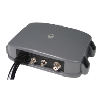
Connect cables for power, VHF antenna, and data to the AIS700 unit and MFD.
Download the ProAIS2 software and the full installation manual for system setup.
Configure the MMSI number, noting US-specific dealer programming requirements.
Install the VHF antenna, adhering to recommended spacing and connection types.
Enable AIS overlays on chart apps for Raymarine a/c/e/gS/eS Series, Axiom, and Element MFDs.
Understand LED indicators for OK, Error, Not transmitting, and Silent mode status.
Use ProAIS2 diagnostics via USB and access the troubleshooting guide for support.
| Type | Class B AIS Transceiver |
|---|---|
| NMEA 0183 Output | Yes |
| NMEA 2000 Compatible | Yes |
| Integrated GPS | Yes |
| Display | No |
| Waterproof Rating | IPX6 |
| Transmit Power | 2 W |
| Receiver Sensitivity | -107 dBm |
| Connections | NMEA 0183, NMEA 2000, USB |
| Interface | NMEA 0183, NMEA 2000, USB |
| Frequency | 161.975 MHz (AIS1), 162.025 MHz (AIS2) |
| Antenna | External |
| Operating Temperature | -15°C to +55°C |