EasyManua.ls Logo

Raymarine AIS4000 - User Manual

Raymarine AIS4000
120 pages
Print Icon
To Next Page IconTo Next Page
Loading...

Table of Contents

Other manuals for Raymarine AIS4000

Questions and Answers

  • Y
    ytranAug 16, 2025
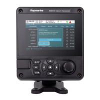
    Why is the red alarm icon flashing on my Raymarine AIS4000 Transceiver?
    • T
      Timothy WilsonAug 16, 2025
      The red alarm icon may illuminate or flash on your Raymarine Transceiver for several reasons: * The unit may not have a valid MMSI: Check that the AIS transceiver is correctly configured with a valid MMSI. * The VHF antenna may be faulty: Check the connection to the VHF antenna and ensure the VHF antenna is not damaged. * No GPS position fix can be obtained: Check the AIS transceiver's location to ensure the internal GPS antenna has a clear sky view, or verify that an external GPS antenna is properly connected and installed. * The power supply is outside the allowable range: Check that the power supply is within the range of 10.8VDC to 31.2VDC. * Check for error and alarm messages in the ‘Alarms’ menu.
  • S
    sjohnsonAug 19, 2025
    How to fix Raymarine AIS4000 when no data is being received by a connected chart plotter?
    • Y
      yodomAug 19, 2025
      If your Raymarine Transceiver is not sending data to the chart plotter, verify that the power supply is correctly connected and is either a 12VDC or 24VDC supply. Also, check that the connections to the chart plotter are correct.
  • K
    Kelly SnyderAug 22, 2025
    Why is my vessel name not showing on other vessels' chart plotters when they receive my Raymarine Transceiver MMSI?
    • R
      Ronald PhillipsAug 22, 2025
      Some older AIS devices and chart plotters do not process the specific class B message which provides the vessel name (message 24). Software upgrades are available for many older chart plotters which will correct this issue. Alternatively, the other vessel should update its AIS unit and / or chart plotting software to receive AIS message 24.
  • L
    Lance MooreAug 25, 2025
    What to do if the screen on my Raymarine Transceiver is not illuminated?
    • D
      dpetersonAug 26, 2025
      If the screen on your Raymarine Transceiver is not illuminated: * Check that the power supply is connected correctly. * Ensure that the power supply is a 12VDC or 24VDC supply. * Press and hold the ‘Navigation status / Screen brightness’ button for at least 5 seconds to return the display to maximum brightness.
  • J
    Jennifer ScottAug 27, 2025
    What causes a VSWR alarm or high VSWR on a Raymarine AIS4000 Transceiver?
    • N
      Nicole WilliamsAug 28, 2025
      A VSWR alarm or high VSWR on your Raymarine Transceiver can be caused by several factors. To resolve this: * Ensure the VHF Antenna is as far away as possible from metallic structures and any other antennae. * Ensure the VHF Antenna is as high as possible. * Ensure the VHF Antenna is suitable for AIS i.e. 3dBi Gain, 156-162MHz, and uses high quality RG213 or RG214 cable. * The VHF Antenna cable should be as short as possible and no more than 30 metres (100ft) in length.
  • E
    Ernest MoralesAug 30, 2025
    Why are external sensors not being recognized by my Raymarine AIS4000 Transceiver?
    • I
      Ivan BentonAug 30, 2025
      If external sensors are not being recognized by your Raymarine Transceiver, check the Compatibility Mode option in the Interface Settings Menu, verify the Baud Rate setting, and ensure the wiring is correct.
  • K
    Kimberly RamosSep 2, 2025
    What to do if the RED ‘Alarm’ icon is illuminated on my Raymarine AIS4000 Transceiver?
    • W
      whitedavidSep 2, 2025
      If the red 'Alarm' icon is illuminated or flashing on your Raymarine Transceiver, ensure that the AIS transceiver is correctly configured with a valid MMSI. Also, verify the connection to the VHF antenna, ensuring it's not damaged. Confirm that the AIS transceiver has a clear view of the sky for the internal GPS antenna or that an external GPS antenna is properly connected and installed. Check that the power supply is within the range of 10.8VDC to 31.2VDC, and review the 'Alarms' menu for any error messages.
  • D
    Dr. John GentrySep 5, 2025
    How to fix Raymarine AIS4000 when no data is being received by the chart plotter?
    • C
      crossSep 5, 2025
      If your Raymarine Transceiver is not sending data to the chart plotter, first, check that the power supply is correctly connected. Then, ensure the power supply is a 12VDC or 24VDC supply. Finally, check that the connections to the chart plotter are correct.
  • K
    Kelly GregorySep 8, 2025
    How to fix the screen if it is not illuminated on my Raymarine AIS4000 Transceiver?
    • D
      Dave BarberSep 8, 2025
      If the screen of your Raymarine Transceiver is not illuminated, verify that the power supply is correctly connected and that it is a 12VDC or 24VDC supply. If the power is ok, press and hold the ‘Navigation status / Screen brightness’ button for at least 5 seconds. The display should return to maximum brightness.
  • M
    Michael CookSep 12, 2025
    What causes VSWR Alarm on Raymarine AIS4000?
    • M
      Monica WillisSep 12, 2025
      If you are experiencing a VSWR Alarm or High VSWR on your Raymarine Transceiver, make sure the VHF Antenna is as far away as possible from metallic structures and any other antennae. Ensure the VHF Antenna is as high as possible. Verify the VHF Antenna is suitable for AIS (3dBi Gain, 156-162MHz, and uses high quality RG213 or RG214 cable). Also, the VHF Antenna cable should be as short as possible and no more than 30 metres (100ft) in length.

Summary

List of Abbreviations

Notices and Warnings

Safety Warnings

Essential safety instructions for installation, performance, and usage.

General Notices

Information on position source accuracy, compass safe distance, and disposal.

Regulatory Statements

Details on FCC, Industry Canada compliance, and CE marking.

Introduction to AIS

About AIS

Explains the Automatic Identification System (AIS) functionality and purpose.

Installation and Configuration

What’s in the Box?

Lists all items included in the AIS transceiver package.

Preparing for Installation

Details necessary external items and considerations before installation.

Installation Procedures

Step-by-step guide for mounting and connecting the AIS transceiver.

Connecting Equipment and Ports

Describes data connections, sensor configuration, and port details.

Power and Grounding

Instructions for connecting power supply and grounding the unit.

Network and USB Connections

Guide for NMEA2000 network and PC/Mac USB connectivity.

Passwords and Security Settings

Explains password entry, security settings, and default password.

Operation Guide

Display and Controls Overview

Identifies front panel controls, display elements, and button functions.

Menu Navigation and Information Display

Details how to navigate menus and understand displayed information and icons.

Alarms and Messages

Explains alarm conditions, status indicators, and message handling.

Vessel and Voyage Configuration

Guides on entering vessel identification and voyage data.

AIS Target Management

How to display, filter AIS targets, and use CPA/TCPA settings.

Data Input and Storage

Describes Micro SD card usage for charts, firmware, and data logging.

WiFi Feature Usage

Explains setting up and using the WiFi network capabilities.

Inland Mode Operation

Inland Mode Settings

Covers switching modes, entering specific inland data, and alarm masking.

Blue Sign Switch Configuration

Details the connection and configuration of the Blue Sign switch.

Technical Information

Interface Circuits and Ports

Describes input/output circuits, port specifications, and dimensions.

Data Transmission and Sentences

Details transmission intervals, NMEA sentences, and unused fields.

Sensor Ports, Compatibility, and Troubleshooting

Explains sensor priority, compatibility modes, and common issues.

Junction Box Accessory

Junction Box Contents

Lists the contents of the junction box accessory kit.

Junction Box Installation and Connections

Guides on mounting the junction box and connecting external equipment.

Junction Box Technical Details

Provides physical, environmental, and connector specifications for the junction box.

Technical Specification

Applicable Equipment Standards

Lists relevant IEC and ITU standards the product complies with.

Product Category and Physical Specs

Details product categorization and physical dimensions/weight.

Environmental and Electrical Specs

Covers operating conditions, humidity, ingress rating, and electrical requirements.

Display, Interface, and Internal Systems Specs

Specs for display, keypad, GNSS, TDMA, DSC, and RF interfaces.

WiFi and Data Interface Specifications

Technical details for WiFi and various data interface ports.

Connector Information and Licences

Information on power/data connectors and open source software licences.

Installation Record

Vessel Details Recording

Forms for recording vessel and installation specific information.

Raymarine AIS4000 Specifications

General IconGeneral
AIS ClassClass B
GPS ReceiverIntegrated
NMEA 0183Yes
NMEA 2000Yes
Waterproof RatingIPX6
Channels2
DSC CapabilityYes
Power Supply10-32 V DC
Frequency161.975 MHz

Related product manuals