Installation and configuration
Page 34
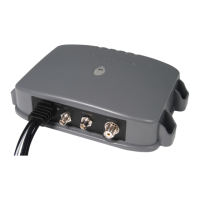
Note: Any unused ports should be terminated by a 120 Ohm resistor across
RX A and RX B signals. COMMON signals should be grounded.
All sensor ports can be configured via the Interface settings menu which can
be found under the ‘Home’ > ‘System settings’ > ‘Interfaces’ menu option.
The Interface settings menu also includes the ability to disable the requirement
for external GNSS sensors to provide a DTM (Datum) sentence.
3.4.6 Alarm connections
The AIS transceiver also provides connections to the alarm relay contacts.
The alarm relay connections are described in Table 4.
Table 3 Alarm relay connections
Alarm connection Function Contact rating
COM Alarm relay common
connection 2A at 220VDC or 60W
maximum
NC Alarm relay normally
closed connection
If an external GNSS device which does not provide a DTM
sentence is connected to the AIS transceiver and the AIS
transceiver is configured to require DTM sentences, the
external GNSS data will not be accepted by the AIS
transceiver. If no DTM sentence is required the WGS84
datum will be used as a coordinate origin and the
external GNSS device must be configured to output
position using this datum.
 Loading...