.
.
-
_-
_
.
.
-
-
.
.
.
-
-
.
SLOPING TILLER
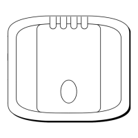
CANTILEVER MOUNTING (Fig.
7)
Where
il
is necessary lo allach lhe
aulopitol lo a
verlical
lace such as lhe
cockpil sidewall a canlilever
sockel
assembly is used.
The maximum exlension
ollsel
is
254mm (IO”) and Ihe canlilever lenglh
can be cul lo the exacl tenglh necessary
during mounling.
lnalatlallon
l
Clamp Ihe
tiller
on the yacht’s cenlre
line.
0 Measure dimension F (aclual)
0
Reler
lo lable lo eslablish culling
length
tar
canlitever rod. (Double
check measuremenls before culling).
Dlmensldn F
___-
---
Cut
Length
L
654nrn
(25.75”)
5
1
mm
(2”)
705mm (27.75”)
102mm
(4”)
743mm (29.75”) 152mm
(6”)
606mm
(31.75”)
203mm
(0”)
632mm (32.75”)
229mm (9”)
l
Cul canlilever rod lo length L using a
hacksaw. Measure lrom lhreaded
end.
0
f7emove
burrs wilh
lile.
l
Temporarily assemble Ihe canlilcvcr
by screwing Itie rod inlo Ihe,mounling
tlange.
l
Ensure Ihe Aulohelm body is
horlzonlel and mark olt the tocalion
01
lhe mounling tlange.
l
Mark and drill 3
x
6mm
(%‘I)
holes
(ignore lhe Iwo inner holes).
l
Mounl Ihe Ilange using 3 x 6mm
(S”)
diameler bolls wilh nuls and washers.
Be sure to
inslall
Ihe backing plale
correclly. Bed Ihe llange on a Ihin coal
01
silicon sealanl.
0 Screw Ihe rod lirmly
inlo
place using a
lommy bar.
0 Roughen Ihe end
01
Ihe rod and Ihe
inside
01
lhe cap lo provide a key.
l
Apply Ihe Iwo
par1
epoxy adhesive
provided lo Ihe rod end and cap and
place Ihe cap over the rod end.
l
Ensure Ihe hole
lor
Ihe Aulohelm
mounling pin is lacing up.
0
Allow Ihe epoxy 30 rninules lo
lully
harden betore applying any load.
When Ihe Aulohelm is nol in
USQ
lhe
cornptele rod assembly may be
unscrewed, leaving Ihe cockpil
unctullered.
 Loading...