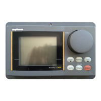
PEDESTAL SOCKET MOUNTIfIG
l
Mark
oil
Ihe
posilion
01
the
mounling
II
may
IJc
necessary lo raise
ItJc
IJeiylJl
01
Ilange on lhe cockpil
seal
01
counler.
Ilie
/LJlolJeirn
rr1o~Jr~liny
sockcl
above
Ihe
l
Ensure
Ihal
co11lrol
dimensions A and
mounting surlace For
Illis
a pedestal
B
are
correcl.
scckel
assembly is used.
l
Mark and drill 3 x
61nm
(N”)
diameter
holes (ignore
II10
Iwo inner holes).
Selecllon
l
I~lounl
Ihe llange using 3 x
Gmrn
(%‘I)
0
Lock Ihe liller on Ihe yachl’s cenlre
tlianieler
bolls.
nuls
and washers.
Ilne tJeing
suie
I110
tJack
plale
is
inslalled
0
EShi
hS1,
IlK?
Skllldi-,lt~
COlJtlCJt
corieclly.
Bed
llie
Ilango
on a
Ilbin
coal
tl~~~rc~~s~o~,s
A
(50911~1~123
2”)
and
0
01
silicon sealanl (Fig. 9).
(.1(3011l111118").
l
Screw Ihe mounling
socke!
lirmly
ir1lo
l
MeaslJJe
dinlension
G (Fig.
6) place.
ensuring Ihe Aulolielm aclualor is
horizontal.
WlJen
Ihe
Pulolteln1
is
no1
in use lhe
l
Selecl
the
appropriale pedeslal
sockel
rnounling
sockel
may be unscrewed
IO
assembly
loom
the
lable
sha,vn.
leave Ihe cockpil unciullcred.
I
DlmenelonQ
.’
-
-
Pedeelel
Socket
Length
i-
-
--.
Cei
Ha.
64mm (2.5”)
Sld
dimensioJ1
__.___
-._.---._
._.-
-.
1021&1(40")
_.
._....
-
._-.
--.
.-_
_
.__
__-_-
_._.__
36riirn (I 5”) DO26
I
l4mm
(4 5”)
50111111 (2.0")
0027
._
_
-.-
_..
.._
_._.
\2Umm (5.0”)
G4n&
g.5”)
_
.._.
i)02u. .
.-_-._-
14Omin
(55”)
..
-
..
76mrn (3 0”)
0029
153rnrn(GO”j
-
-
-
-
--.
09it~l,l(i5~fj
.
._._
_--
..-.
“ojo-.
__-.
.._----
_
-..
.
TILLER PIHS
For cerlain nondandarrl installations a
range
01
liller
lJins
are available.
.
Deecrlpllon
Sire Cal flo.
Small
\hJeacjerl
liller pin
25rlllrl(I")
DO14
-Exlia
len~ll; liller pin
_
.._
.
_
72rl1111
(2.0”) 0020
-
_
_
Exlra Ienglh ~hre&&J tiller pin
-
--
72111111
(2.0”)
-.
-
. . ..---. --_ _..-.
.
.._.___
._
. . -...
._
0021
Batlery
Connecllon
The walerprool ‘DriPlug’ supplied
should be silualcd as close as possible lo
minimise lead lenglh. The D&Plug
sockel
musl be connecletl dlreclly lo
II10
vessels
eteclrical
dislrib~rlion
panel
aid
on no accoiJnl paralleled
inlo
oxisling
wiring
lor
olher
equipmenl.
The
AulolJeltn
SulJlJly
n1usl
be
independanlly
swilclied
and
prolecletl
by
a 5 amp luse or currenl
lrip.
Since
the
aulopilot is micfoprocessor
based
il
is very iiriporlanl lhal vollage
losses in supply cables are ininirniscd.
Supply cables should Ilierclotc be as
sl1orl
as possible and
01
no less size Ihan
shown in lhe lollowing
lable.
The brown wire
01
Iho
power-supply
lead should be connecled to poslllve II
conneclions
arc
accitlcnlly reversed Ilte
alJlolJilol
will
no\
operalc bul no damage
will
resull.
_.
-
._..
__.
-.__
..____..
Lead
Lenglli
-_..
-
-.._
.-.
_--_.
up
lo
2.5111(W)
. .
-_
Uplo
4
Olll(13')
-.
. .
.-.
. . .
_-...
up lo
fxl1l(22’)
Copper Area
-1
bl-,d
Lild
'2.immi
9
 Loading...