2.2.3 HYDRAULIC DRIVE UNIT
The hydraulic drive unitshould be mounted
clear of spraj/ and the possibility of immersion
in water. It should be located as near as
possible to the hydraulic steering cylinder. It is
important to bolt the hydraulic drive unit
securely to a substantial member to avoid any
possibility of vibration that could damage the
inter-connecting pipework.
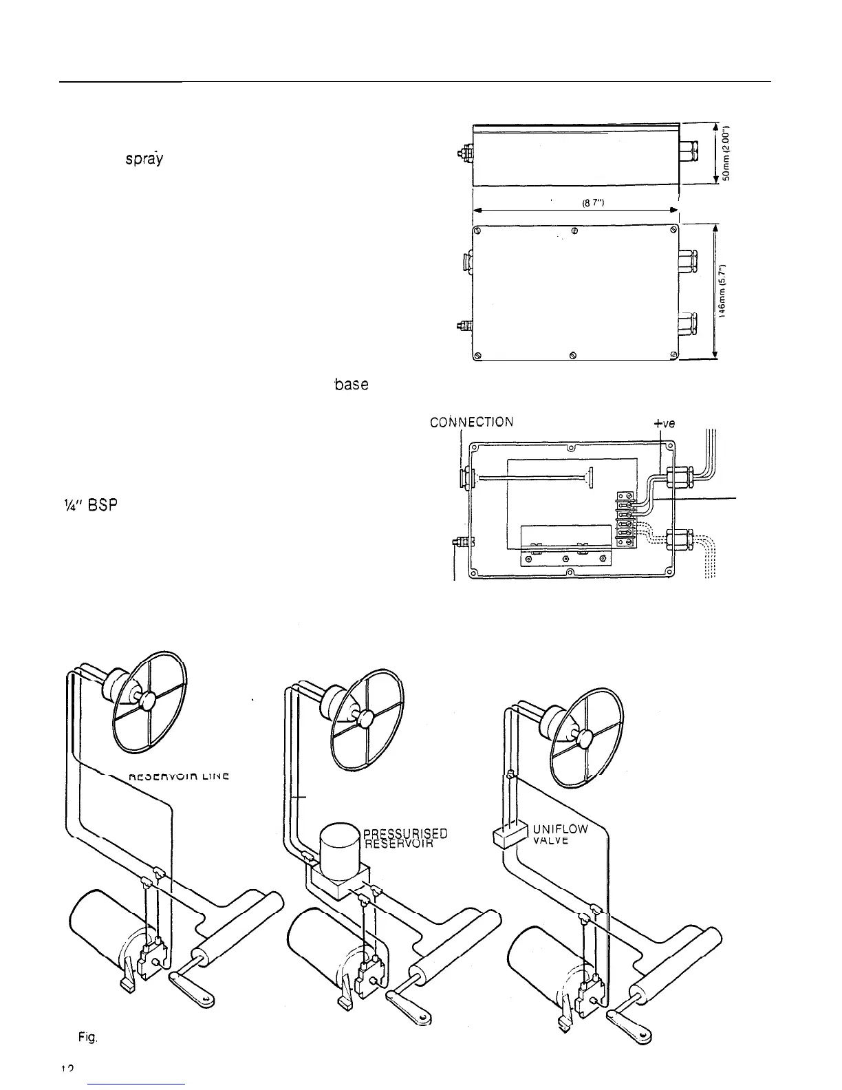
The drive amplifier (Fig. 13) should be
mounted between the drive unit and the power
supply (batteries) in order to minimise the total
length of power cable. It should also be
mounted in a position clear of bilge water and
spray. The drive amplifier is mounted by first
removing the cover marked ‘Autohelm’ and
bolting or screwing to a suitable vertical
bulkhead through the four holes in the
.base
(Fig. 14).
There are three basic types of hydraulic
steering system (Fig. 12). Typical connection
points for the drive unit are shown in each case.
In all cases it is strongly recommended that
the steering gear manufacturer be
consulted. The drive unit valve block is tapped
l/4”
BSP
to accept suitable pipe fittings and
Dowty sealing washers are supplied (Fig. 15).
CONTROL UNIT
POWER SUPPLY CABLE
COiVfylECTlON SOCKET
fve
I
Two Line System
222mm
(8
7”)
*
8
Fig. 13 Drive Amplifier
I
DRIVE UNIT
EARTHING TERMINAL CONNECTION
Two Line
Pressurised System
-RESERVOIR LINE
-ve
Fig. 14 Drive Amplifier Wiring Diagram
.
Three Line System
PRESSURISED
w
Fig.
12
RESERVOIR LINE
 Loading...