Minimisation of hydraulic fluid loss during
connection of the drive unit will help to reduce.
the time and effort required later to bleed the
system of trapped air. Absolute cleanliness is
essential since even the smallest particle of
foreign matter could interfere with the correct
function of precision check valves in the
steering system.
When the installation has been completed
the hydraulic pump may be operated by
switching the control unit to Duty and operating
the Steer control. Greater motor movements will
be obtained if the gain control on the course
computer is set to No. 10 and the rudder
control set to maximum.
The hydraulic steering system should be
bled according to the manufacturer’s
instructions. From time to time during the
bleeding process the drive unit should be run
in both directions to clear trapped air from the
pump and inter-connecting pipe work.
If air is left in the system the steering will
feel spongy particularly when the wheel is
rotated to the hardover position. Trapped air will
severely impair correct operation of the
autopilot and the steering system and must be
removed.
During the installation of the system it has
not been necessary to keep track of the
connection sense to the hydraulic steering
circuit since operating sense of the autopilot
can be corrected if necessary by reversing the
polarity of*
pump
drive motor connections
(see section 3.3.1).
To check correct phasing of
the_autopilot,
switch to Duty and rotate the Steer control
clockwise. If phasing is correct starboard
rudder movement will result. If opposite rudder
movement occurs, reverse the phase switch
direction to correct as described in Section 3.2.
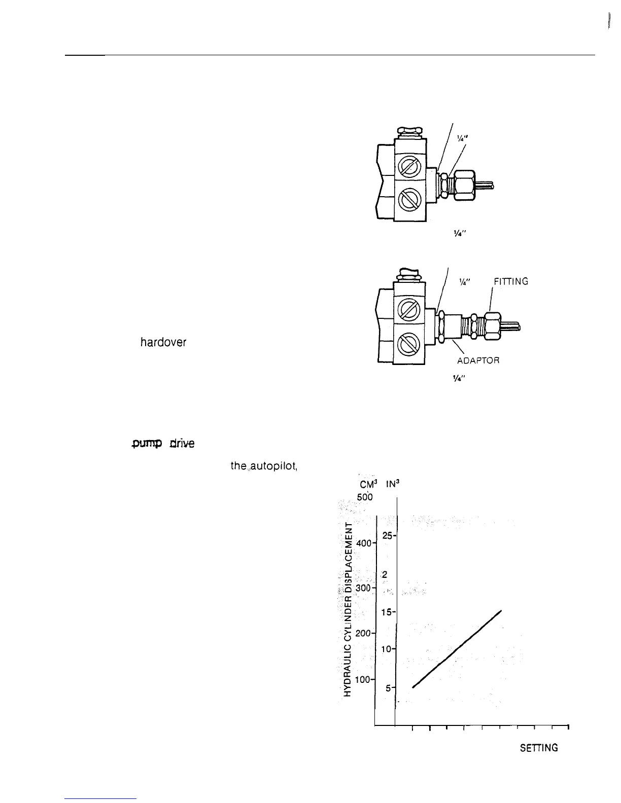
The gain control located on the back of the
Control, Unit sets the rudder response of the
autopilot to match the particular installation.
The recommended gain control setting is given
in Fig. 16.
CONNECTION OF
HYDRAULIC LINES TO PUMP
DOWTY SEAL
’
BSP FITTING
Assembly for W’ BSP Line Fitting
Fig. 15
DOWTY SEAL
-
I
#=%I
‘h” NPT FllTlNG
Assembly for
l/d’
NPT Line Fitting
ii3
IN3
RECOMMENDED GAI
50b
30-
1
CONTROL SETTINGS
5-
O-
1
_#”
__.ii.
15
/
N
I
I
I
II
”
11
1
1
2 3
4 5
6 7
8 910
GAIN CONTROL AVERAGE SE-tllNG
Fig. 16
13
 Loading...