vi
List of Figures
Figure Page
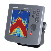
Unit in Use Inside front cover
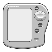
Front Panel i
1-1 Typical Installation 1
2-1 Transducer Types 5
2-2 Assembling the Transducer Bracket 6
2-3 Transducer Mounted on Transom 7
2-4 Transducer Bracket, Side View 7
2-5 Correct Mounting Position 8
2-6 Mounting the Transducer 8
2-7 Installing the Sidelooker Transducer 10
2-8 Installing the Sidelooker Transducer -
Trolling Motor 13
2-9 Installation on Bracket 14
2-10 Dimensions 15
2-11 Flush-Mount Installation 16
2-12 Disassembling from Bracket 17
2-13 Installing Cable on Transom 18
2-14 Cable for Sidelooker Transducer 19
2-15 Cable for Speed and Temperature Sensor 20
2-16 DC Power Connections 21
3-1 Display Panel 24
3-2 Lamp/Contrast Menu 26
3-3 Selecting DisplayPages 27
3-4 FishFinder Page 29
3-5 Fish Indications 36
3-6 Bottom Conditions 37
3-7 Zoom Page 38
3-8 A-Scope Page 40
3-9 Digital Page 42
3-10 Sidelooker Feature 43
3-11 Sidelooker Page 44
4-1 Moving Through the Setup Menu 47
4-2 Range Settings 48
4-3 Sensitivity Setting 49
4-4 Changing the Chart Speed Setting 50
4-5 Chart Speed Setting 51
4-6 Zoom Settings 52
4-7 Frequency Setting 53
4-8 Resetting the Log 54
4-9 Reaching the System Setup Display 55
4-10 System Setup Display 55
4-11 Sidelooker Range Settings 61
4-12 Sidelooker Sensitivity Settings 62
5-1 Sample Mailing Label 70
6-1 Connector Diagrams 74

 Loading...


