18
Table G: Heater Rates of Flow and Pressure Drops
Notes: 1. Basis for minimum flow is 40°F ∆T. Basis for maximum flow is 132 GPM.
2. Rear-mounted pumps may provide higher flow rates on smaller models than the system requirements
Feedwater Regulator
Raypak recommends that a feedwater regulator be in-
stalled and set at 12 psi minimum pressure at the
highest point of the system. Install a check valve or
back flow device upstream of the regulator, with a
manual shut-off valve as required by local codes.
Piping
All high points should be vented. Purge valves and a
bypass valve should be installed. A heater installed
above radiation level must be provided with a low wa-
ter cut-off device (sales order option F-10). The heater,
when used in connection with a refrigeration system,
must be installed so that the chilled medium is piped in
parallel with the heater with appropriate valves to pre-
vent the chilled medium from entering the heater.
The piping system of a hot water heater connected to
heating coils located in air handling units where they
may be exposed to circulating refrigerated air, must be
equipped with flow control valves or other automatic
means to prevent gravity circulation of the heater
water during the cooling cycle. It is highly recommend-
ed that the piping be insulated.
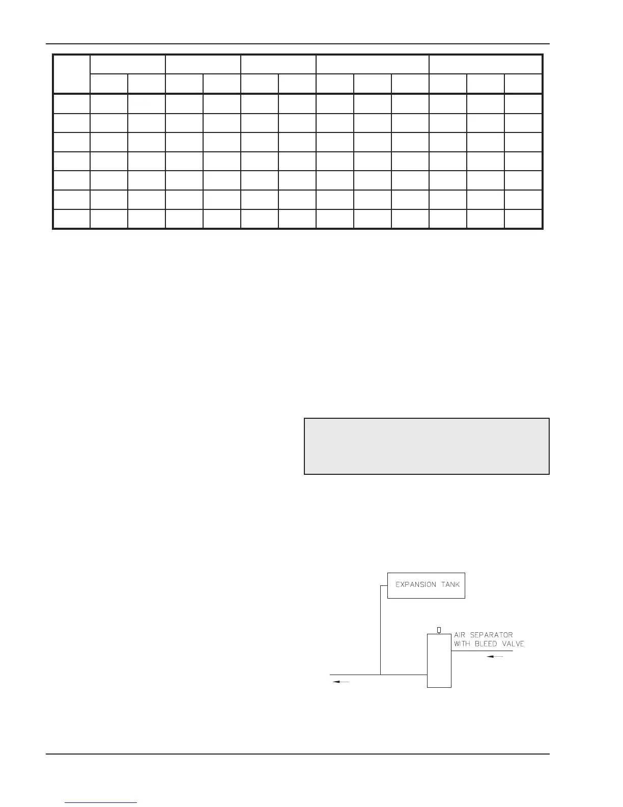
Air-Separation/Expansion Tank
All heaters should be equipped with a properly sized
expansion tank and air separator fitting as shown in
Fig. 14.
System Sensor Installation
The System Sensor (S3) is required for all selectable
mode unless the unit’s firing rate will be controlled by
Fig. 14: Air-Separation/Expansion Tank
an external source such as the Temp Tracker MOD+
Hybrid sequencer (sales option B-36). Proper place-
ment and method of installation are critical for proper
operation of the system. (See Fig. 7) The sensor must
be installed in a drywell in conjunction with heat con-
ductive compound as shown in the following images.
The drywell must be installed no more than 5 equiva-
lent feet of pipe/tubing downstream of the de-coupler
and installed in such a way that ensures the sensor
bulb is in the flow path.
Three-Way Valves
Valves designed to blend water temperatures or
reduce water circulation through the heater should not
be used. Raypak heaters are high-recovery, low-mass
heaters which are not subject to thermal shock.
Model
N
o.
2
0ºF∆T
3
0ºF∆T
3
9ºF∆T
M
in. Flow
M
ax. Flow
gpm ∆P (ft) gpm ∆P (ft) gpm ∆P (ft) gpm ∆P (ft) ∆T gpm ∆P (ft) ∆T
992C 83 5.2 55 2.3 43 1.4 43 1.4 39 132 13.1 13
1262C 106 9.6 71 4.3 54 2.5 54 2.5 39 132 14.8 16
1532C 129 15.7 86 7.1 66 4.2 66 4.2 39 132 16.5 19
1802C N/A N/A 101 10.7 78 6.3 78 6.3 39 132 18.3 23
2002C N/A N/A 112 13.8 86 8.3 86 8.3 39 132 19.0 25
2072C N/A N/A 116 14.8 89 8.9 89 8.9 39 132 19.0 26
2342C N/A N/A 132 21.1 101 12.7 101 12.7 39 132 21.4 30
CAUTION: Be careful when installing the drywell
not to over-tighten the well as this can damage the
well and may prevent the sensor from fitting
property.
 Loading...