EasyManua.ls Logo

Raypak 185 User Manual

Raypak 185
14 pages
To Next Page IconTo Next Page
Page #1 background imageLoading...
Page #1 background image
OPERATING AND
INSTALLATION
INSTRUCTIONS
Models
185, 265, 335, 405
Swimming Pool and Spa Heaters
181/182, 260/261, 330/331, 400/401
Water Heaters and Boilers
D-2 POWER VENT
(FOR ELECTRONIC IGNITION MODELS ONLY)
CATALOG NO. 6000.57D
Effective: 10-26-06
Replaces: 03-15-03
FOR YOUR SAFETY
Do not store or use gasoline or other flammable vapors and liquids or other combustible
materials in the vicinity of this or any other appliance. To do so may result in an explosion
or fire.
WARNING: Improper installation, adjustment, alteration, service or maintenance can cause
property damage, personal injury or loss of life. Refer to the user’s information manual
provided with this heater. Installation and service must be performed by a qualified in-
staller, service agency or the gas supplier.
FOR YOUR SAFETY
WHAT TO DO IF YOU SMELL GAS:
· Do not try to light any appliance.
· Do not touch any electrical switch; do not use any phone in your building.
· Immediately call your gas supplier from a neighbor’s phone. Follow the gas
suppliers instructions.
· If you cannot reach your gas supplier, call the fire department.
This manual should be maintained in legible condition and
kept adjacent to the appliance or kept in a safe place for
future reference.
P/N 241086 Rev. 1
Question and Answer IconNeed help?

Do you have a question about the Raypak 185 and is the answer not in the manual?

Raypak 185 Specifications

General IconGeneral
BrandRaypak
Model185
CategoryWater Heater
LanguageEnglish

Summary

D-2 Power Vent Safety and Warnings

General Safety: Flammable Vapors

Avoid storing flammable vapors near the appliance to prevent explosion or fire hazards.

Installation and Service Warning

Improper installation or service can cause damage or injury; use qualified personnel only.

Gas Leak Emergency Procedure

Instructions for gas leaks: Do not light appliances, use phones, or touch switches. Call gas supplier.

Power Vent Assembly: Receiving and Specifications

Receiving Equipment Inspection

Check carton for external damage upon receipt and report any damage to the carrier immediately.

General Specifications Overview

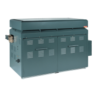
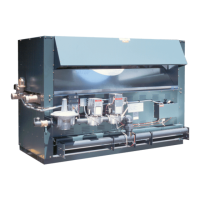
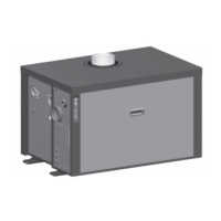
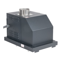
Details about the D-2 Power Vent Assembly, its testing, certification, and design for specific Raypak models.

Installation Requirements and Mounting

Installation Code Compliance

Equipment must be installed per local codes and National Fuel Gas/Electrical Codes.

Power Vent Mounting Procedure

Step-by-step instructions for physically attaching the Power Vent to the heater unit.

Power Vent Mounting and Wiring

Mounting Power Vent Assembly (Continued)

Further steps for mounting the Power Vent assembly, including securing it to the vent.

Wiring for IID Ignition Systems

Instructions for connecting the Power Vent assembly wiring to an appliance with IID ignition.

Venting Guidelines and Recommendations

Vent Pipe Specifications

Guidelines on vent pipe size, rotation, pressure, and temperature limits for D-2 Power Vent.

Preventing Vent Condensate Accumulation

Recommendations for vent slope and insulation to prevent condensate accumulation.

Cold Climate Venting Considerations

Specific recommendations for vent slope and condensate traps in extreme cold climates.

Specific Venting Applications

Through-the-Wall Venting Suitability

Suitability of the D-2 Power Vent for through-the-wall installations and smaller vent pipes.

Wire Harness for Control Connections

Details on the wire harness for quick connections to heater controls.

Heater Operation Sequence

Operational Sequence Overview

Describes the step-by-step process from call for heat to heater shutdown.

Start-Up and Emergency Procedures

Safe Start Up Procedures

Step-by-step guide to safely start the heater and check its operation.

Emergency Shutdown Protocol

Procedure for immediate shutdown in case of emergency.

Draft Proving Switch Role

Explains the role of the draft proving switch in ensuring blower operation for ignition.

Illustrated Parts List

Component Identification and Part Numbers

List of parts with call-out numbers for the 181-265 and 331-405 models.

Related product manuals