INSTALLATION & OPERATING
INSTRUCTIONS
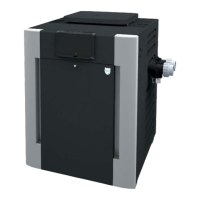
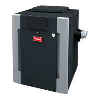
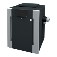
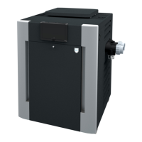
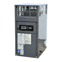
Gas-Fired
Pool & Spa
Heater
Catalog No. 6000.59U Effective: 10-06-10 Replaces: 06-10-10 P/N 241236 Rev. 22
WARNING: If these instructions are not followed exactly, a fire or explosion may result
causing property damage, personal injury or death.
WHAT TO DO IF YOU SMELL GAS:
• Do not try to light any appliance.
• Do not touch any electrical switch; do not use any phone in your building.
• Immediately call your gas supplier from a neighbor's phone. Follow the gas sup-
plier's instructions.
• If you cannot reach your gas supplier, call the fire department.
Installation and service must be performed by a qualified installer, service agency or
the gas supplier.
This manual should be maintained in legible condition and kept adjacent to the heater or in a safe place for future
reference.
Atmospheric Models
206A, 266A, 336A & 406A
Lo NOx Models
207A, 267A, 337A & 407A
Do not store or use gasoline or other flammable vapors and liquids in the vicinity of
this or any other appliance.