EasyManua.ls Logo

Raypak P-R266A-EN-C

Raypak P-R266A-EN-C
56 pages
To Next Page IconTo Next Page
Loading...
INSTALLATION & OPERATING
INSTRUCTIONS
Gas-Fired
Pool & Spa
Heater
Catalog No. 6000.59AB Effective: 03-15-17 Replaces: 08-15-15 P/N 241236 Rev. 29
WARNING: If these instructions are not followed exactly, a fire or explosion may result
causing property damage, personal injury or death.
WHAT TO DO IF YOU SMELL GAS:
Do not try to light any appliance.
Do not touch any electrical switch; do not use any phone in your building.
Immediately call your gas supplier from a neighbor's phone. Follow the gas sup-
plier's instructions.
If you cannot reach your gas supplier, call the fire department.
Installation and service must be performed by a qualified installer, service agency or
the gas supplier.
This manual should be maintained in legible condition and kept adjacent to the heater or in a safe place for future
reference.
Atmospheric Models
206A, 266A, 336A & 406A
Lo NOx Models
207A, 267A, 337A & 407A
Do not store or use gasoline or other flammable vapors and liquids in the vicinity of
this or any other appliance.

Table of Contents

Question and Answer IconNeed help?

Do you have a question about the Raypak P-R266A-EN-C and is the answer not in the manual?

Raypak P-R266A-EN-C Specifications

General IconGeneral
ModelP-R266A-EN-C
TypeGas Heater
Heating Capacity266, 000 BTU
Heat Exchanger MaterialCopper
Ignition TypeElectronic
Efficiency82%
Thermal Efficiency82%
Maximum Working Pressure50 PSI
Weight250 lbs
Fuel TypeNatural Gas
ThermostatDigital
Gas TypeNatural Gas / Propane
Water Connection Size2 inches
Output BTU266, 000 BTU/hr

Summary

Important Safety Warnings

General Safety and Gas Leak Precautions

Critical warnings about fire, explosion, and gas leak procedures.

Start-Up Procedures

Pre-Start-Up Checks

Essential checks before initiating the heater start-up sequence.

Millivolt System Operation

Manually Lighting the Pilot

Step-by-step instructions for safely lighting the pilot.

Electronic Ignition System Operation

Automatic Pilot Lighting Procedure

Steps for operating the heater with automatic pilot ignition.

Post Start-Up Checks and Cautions

Visual Inspection and Water Pressure Checks

Verifying flame appearance and water pressure switch function.

Maintenance and Care

General Specifications and Installation Safety

Installation Warnings and Code Compliance

Critical safety notices and adherence to local installation codes.

Installation Clearances

Clearances from Combustible Surfaces

Required minimum clearances from combustible materials for safety.

Outdoor Installation Clearances and Warnings

Specific clearance requirements and warnings for outdoor installations.

Venting and Building Clearances

Indoor Heater Installation

Indoor Installation Requirements and Venting

Specific instructions for indoor installations, including drafthood use.

Combustion Air and Vent Piping

Venting and Gas Supply Connections

Gas Supply Requirements and Testing

Gas supply connection, pressure, and leak testing procedures.

Gas Pressure and Pipe Sizing

Gas Pressure Regulator Adjustment

Procedure for adjusting the gas pressure regulator.

Gas Pipe Sizing Chart

Table for determining correct gas pipe sizing based on length.

Bypass and Pressure Relief Valves

Pressure Relief Valve Installation

Procedure and requirements for installing a pressure relief valve.

Electrical Wiring

Millivolt Model Wiring Connections

Wiring requirements for millivolt heaters.

AFT Model Field Wiring

Instructions for wiring AFT models, including transformer relocation.

Transformer Wiring Diagrams

Millivolt Wiring Diagram

Mechanical Thermostat Wiring Details

Detailed wiring schematic for millivolt mechanical thermostat models.

Atmospheric Wiring Diagram

115240 Volt Operation Wiring

Wiring schematic for atmospheric models.

Lo NOx Wiring Diagram

120240 Volt Operation Wiring

Wiring schematic for Lo NOx models.

Servicing Controls

Atmospheric Model Control Locations

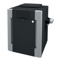
Identifying key control components on atmospheric heaters.

Lo NOx Model Control Locations

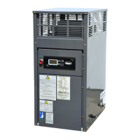
Identifying key control components on Lo NOx heaters.

Control Panel and Adjustments

AFT Thermostat Operation

AFT Control Programming

Status and Diagnostic Messages

Troubleshooting Fault Codes

Identifying and diagnosing fault conditions.

Remote Control Operation

Remote Control Wiring

Time Clock and Pressure Switch

Water Pressure Switch Adjustment

Procedure for adjusting the water pressure switch.

Component Removal and Servicing

Troubleshooting Common Issues

Mechanical Problems and Solutions

Diagnosing and resolving mechanical issues listed in the table.

Millivolt Electrical Troubleshooting

Millivolt Gas Valve Troubleshooting Chart

Flowchart for diagnosing issues with millivolt gas valves.

Electronic Ignition Troubleshooting

IID Troubleshooting Flow Chart

Step-by-step guide for troubleshooting electronic ignition systems.

Control Logic Flow Chart

Related product manuals