EasyManua.ls Logo

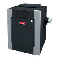
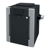
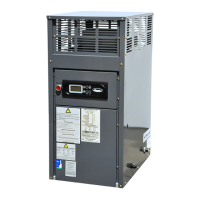
Raypak P-R266A-ENX

Raypak P-R266A-ENX
52 pages
To Next Page IconTo Next Page
Loading...
Gas-Fired Pool
and Spa Heater
E󰀨ective: 11-10-21
Replaces: 08-27-21
P/N 241236 Rev. 41
A
S
M
E
HLW
INSTALLATION AND
OPERATION MANUAL
Bronze ASME and Polymer
Atmospheric Heat Exchanger Models
206A, 266, 266A, 336A, 399, and 406A
This manual should be maintained in legible condition and kept adjacent to the heater or in a safe place for future
reference.
A
WARNING: If the information in the instructions is not followed exactly, a re or explosion may result
causing property damage, personal injury or death.
- Do not store or use gasoline or other flammable vapors and liquids or other combustible materials in
the vicinity of this or any other appliance. To do so may result in an explosion or fire.
- WHAT TO DO IF YOU SMELL GAS
• Do not try to light any appliance.
• Do not touch any electrical switch; do not use any phone in your building.
• Immediately call your gas supplier from a neighbor’s phone. Follow the gas supplier’s instructions.
• If you cannot reach your gas supplier, call the fire department.
- Installation and service must be performed by a qualified installer, service agency or the gas supplier.
BR models only
PRELIMINARY
UNCONTROLLED DOCUMENT IF PRINTED
Question and Answer IconNeed help?

Do you have a question about the Raypak P-R266A-ENX and is the answer not in the manual?

Raypak P-R266A-ENX Specifications

General IconGeneral
ModelP-R266A-ENX
CategoryGas Heater
BrandRaypak
Input (BTU/hr)266, 000
Fuel TypeNatural Gas
Ignition TypeElectronic
Voltage120V
Heat ExchangerCopper
Water Connection Size2 inch
Water Connections2 inch

Summary

1. Warnings

3. Before Installation

4. Installation

Clearances

Details minimum clearances from combustible surfaces for indoor and outdoor installations.

Outdoor Heater Installation

Design certification for outdoor use and warnings about water spray and proximity to heat pumps.

Combustion and Ventilation Air

Specifications and Dimensions

Vent Piping

Gas Supply Connections

Supply Pressure

Specifies minimum and maximum upstream pressure requirements for natural and propane gas.

Gas Pressure Adjustment Locations

Pipe Sizing for Gas Connection

Flow Rate

Provides tables for minimum/maximum flow rates and pressure drops for residential models.

Pressure Relief Valve Installation

Plumbing Diagrams

Water Connection

Illustrates single and multiple heater installation plumbing diagrams for water connections.

5. Electrical Wiring

Electrical Power Draw

6. Wiring Diagram - Millivolt

7. Wiring Diagram - Digital

8. Controls

Control Adjustments - Millivolt Models

Explains how to adjust the water temperature setpoint using the thermostat and knob stop.

Control Adjustments - Digital Models

Guides on using the touch-pad to select modes and adjust setpoint temperatures for digital controls.

Status and Diagnostics

Remote Control Installation and Operation

Water Pressure Switch

Water Pressure Switch Adjustment

Procedure for adjusting the water pressure switch to ensure proper operation based on installation location.

Flame Roll-Out Safety Switch

Heat Exchanger Removal

Unitherm Governor (U.G.) Replacement

9. Operating Instructions

Before Start-Up

Pre-operation checks including clearing the area and ensuring water flow.

Start-Up Procedures

Guides on operating the heater using the control center for pool or spa settings.

Water Pressure Switch

Explains the function of the water pressure switch and the importance of checking its operation.

Operating Instructions and Shutoff Procedures Millivolt System (Manually-Lighted Pilot)

Operating Instructions and Shutoff Procedures Electronic Ignition Digital Models (Automatically-Lighted Pilot)

10. Maintenance and Care

Cold Weather Operation

Guidelines for operating the heater during cold spells and warnings about freeze protection.

Winterizing the Pool and Spa Heater

Step-by-step procedure for shutting down and winterizing the heater in freezing climates.

11. Troubleshooting

Millivolt - Flow Chart

Digital - Flow Chart

Control Logic - Flow Chart - Digital

12. Replacement Parts

13. Illustrated Parts List

Related product manuals