14
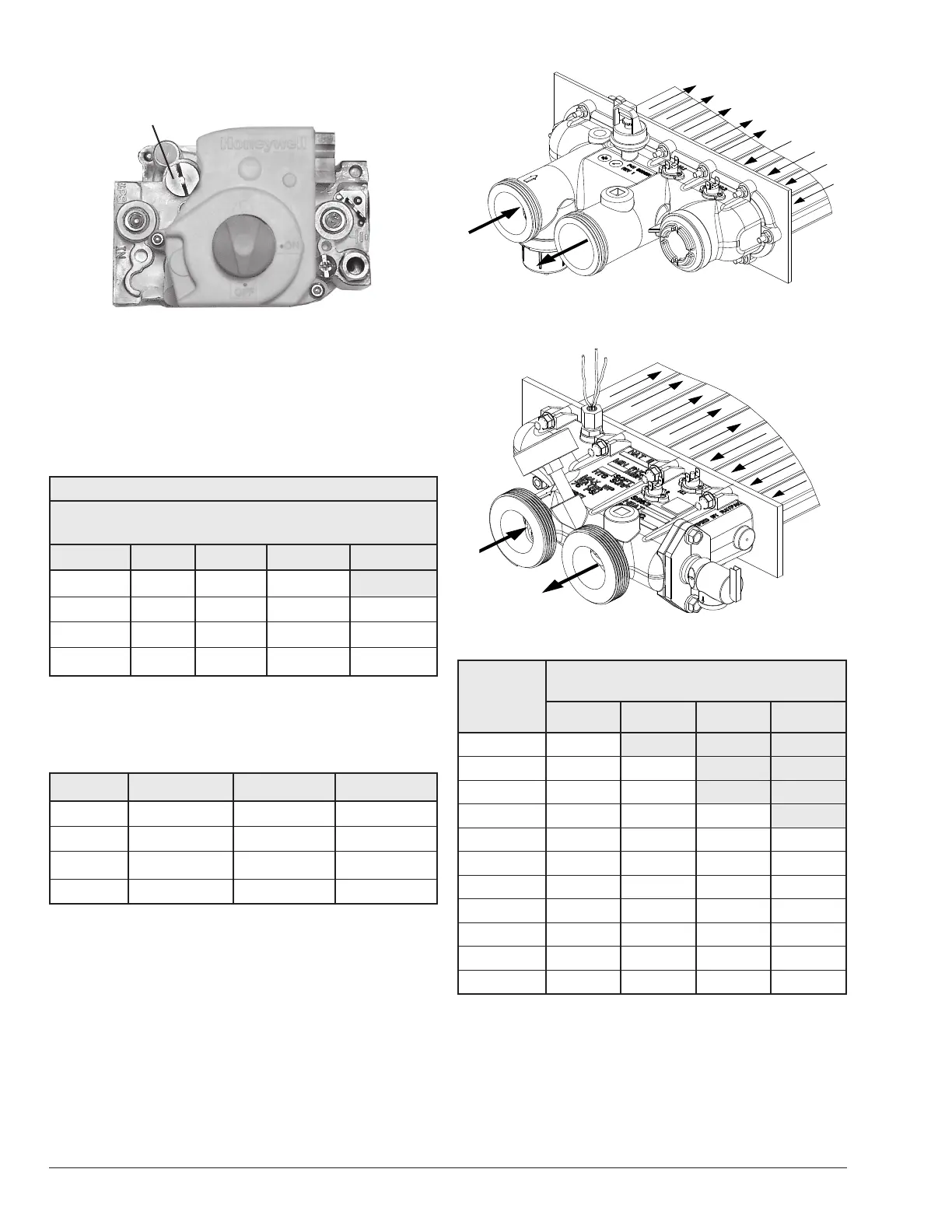
Gas Pressure Adjustment Locations
Gas Pressure Adjustment
Figure 14. Honeywell VR8340
Pipe Sizing for Gas Connection
The capacities shown below are based on using SCH
40 black iron pipe. For capacities using other materials,
consult local codes.
Maximum Equivalent Pipe Length (ft) (m)
Natural Gas 1000 BTU/FT
3
0.60 Specic Gravity @ 0.5 in.
WC Pressure Drop
Model 3/4" 1" 1-1/4" 1-1/2"
207A 25 (7.6) 90 (27.4) 360 (109.7)
266L/267A 15 (4.6) 50 (15.2) 210 (64.0) 445 (135.6)
337A 10 (3.0) 30 (9.1) 140 (42.7) 290 (88.4)
399L/407A * 20 (6.1) 95 (29.0) 215 (65.5)
* A 3/4" gas line can be used for up to 5' (1.5 m) maximum length from the gas
valve in addition to the sediment trap.
Table I. Gas Pipe Sizing
Flow Rates
Model Pipe Size Min. GPM (lpm) Max. GPM (lpm)
207A 1-1/4"–1-1/2"–2" 20 (75) 100 (378)
266L/267A 1-1/4"–1-1/2"–2" 25 (95) 100 (378)
337A 1-1/4"–1-1/2"–2" 35 (132) 100 (378)
399L/407A 1-1/4"–1-1/2"–2" 40 (151) 100 (378)
* When ow rates exceed maximum GPM an external auxiliary bypass valve is
required. See external bypass valve section for details.
Table J. Min/Max Flow Rates
Figure 15. Polymer Headers Water Flow
F10637-1
Figure 16. Bronze Headers (ASME) Water Flow
Flow GPM
(lpm)
Pressure Drop
Ft. of Head (m of Head)
207A 266L/267A 337A 399L/407A
20 (75) 4.0 (1.2)
25 (95) 4.0 (1.2) 4.6 (1.4)
30 (113) 4.0 (1.2) 5.2 (1.6)
35(132) 4.0 (1.2) 5.8 (1.8) 5.2 (1.6)
40 (151) 4.6 (1.4) 5.8 (1.8) 5.2 (1.6) 5.2 (1.6)
50 (189) 4.6 (1.4) 6.3 (1.9) 6.9 (2.1) 6.9 (2.1)
60 (227) 4.6 (1.4) 6.9 (2.1) 6.9 (2.1) 6.9 (2.1)
70 (265) 4.6 (1.4) 8.1 (2.5) 9.2 (2.8) 9.2 (2.8)
80 (303) 4.6 (1.4) 9.2 (2.8) 9.8 (3.0) 9.8 (3.0)
90 (340) 6.9 (2.1) 10.4 (3.2) 10.4 (3.2) 10.4 (3.2)
100 (378) 8.1 (2.5) 11.0 (3.4) 12.1 (3.7) 12.1 (3.7)
Table K. Polymer Heat Exchanger Pressure Drop -
Residential Models (UG Fully Open)
 Loading...