11
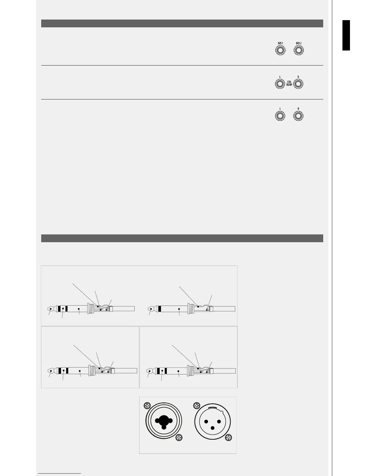
1/4” JACK CONNECTOR
XLR / COMBO CONNECTOR
Connector pinout:
1 = earth
2 = audio signal (+ or „hot“)
3 = audio signal (– or „cold“)
Jack/XLR
Combo Connector (F)
XLR Connector (M)
Sleeve
Ring
Tip
Sleeve = Ground
Ring = Right Channel
Tip=Left Channel
PHONES (TRS)
Sleeve
Ring
Tip
Sleeve = Ground
Sleeve = Ground
Sleeve = Ground
Ring = Signal Return
Tip = Signal Send
INSERT (TRS)
Sleeve
Sleeve
Tip
Tip
Ring
Tip = Hot
Ring = Cold
BALANCED (TRS) UNBALANCED (TS)
Tip = Hot
1 2
3
2
3
1
ENGLISH
REAR PANEL FUNCTIONS
REAR PANEL FUNCTIONS
[39] BUS1 AND BUS2 OUTPUT
These two balanced TRS jacks perform +4dB audio out coming from BUSSES 1 and 2. The audio level of BUSSES
1 and 2 are controlled by the dedicated BUS 1/2 fader located on the front panel (see section 28 on front panel
description).
[40] CTRL ROOM OUTPUT
Connect to the Control Room output Balanced Jacks a pair of studio monitors as a local listening system. The audio
level of the CTRL ROOM output is controlled by the dedicated CONTROL ROOM potentiometer on the front panel
(see section 14 on front panel description).
[41] MAIN MIX L AND R JACKS OUTPUT
These TRS Jacks provide +4dB MAIN MIX output. (See section 36 for details).