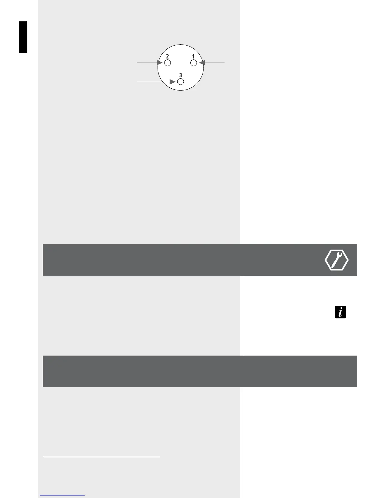
The XLR connectors use the following AES standard:
PIN 1 = GROUND (SHIELD)
PIN 2 = HOT (+)
PIN 3 = COLD (-)
On the back panel you will find all the controls, the signal and current inputs. At first verify
that the voltage selector on the speaker is in proper position for your country (115 Volt or
230 Volt).
The switch shall be in proper position (unless moved from unauthorized people), but a
fast check will avoid problems. In case changing the voltage is necessary, please call your
vendor or authorized RCF SERVICE CENTRE. This operation requires the substitution of the
fuse value and is reserved to an RCF SERVICE CENTRE.
At this point you can connect the power supply cable and the signal cable, but before
turning on the speaker make sure that the volume control is at the minimum level (even
on the mixer output). It is important that the mixer is already ON before turning on the
speaker. This will avoid damage to the speakers and noisy “bumps” due to turning on parts
on the audio chain. It is a good practice to always turn on speakers at last and turn them
off immediately after the show.
Now you can turn ON the speaker and adjust the volume control to a proper level.
CONNECTIONS
BEFORE CONNECTING
THE SPEAKER
BEFORE TURNING ON
THE SPEAKER
HOT GND
BAL. XLR
COLD
VOLTAGE SETUP
(RESERVED TO THE RCF SERVICE CENTRE)
Sub Series active speakers are equipped with a complete system of protection circuits. Two
leds on the amplifier back panel indicate the working status of the amplifier: the green led
indicates the speaker is ON and the red led is on when the protection circuit is active. The
circuit is acting very gently on audio signal, controlling level and maintaining distortion at
acceptable level. If this led stays ON for a long period it is better to reduce immediatelys
the signal level from the mixer or from the speaker volume control.
230 Volt, 50 Hz SETUP: FUSE VALUE T3,15 A - 250V
115 Volt, 60 Hz SETUP: FUSE VALUE T6,30 A - 250V
PROTECTIONS
A 35 MM socket for mounting the loudspeaker on a speaker stand is provided on the top
of the cabinet.
IMPORTANT NOTES
Never suspend SUB speakers by their handles. Handles are intended for transportation, not
for rigging.
INSTALLATION
IMPORTANT NOTES