5
LICC LOW IMPEDANCE COMPENSATED CROSSOVER
All our passive speakers are equipped with high power handling low impedance crossover designs. The low
impedance compensated crossover is an RCF first, and a breakthrough in crossover design. Conventional passive
crossovers have an approximate 180 degree phase shift between the woofer and tweeter at the crossover point.
Such a system cannot reproduce transients correctly, causing negative effects on sound accuracy that are
particularly noticeable with violin, trumpet, piano and vocals. Very low inductance values are used in the LICC, thus
providing an excellent transient response and drastically reducing phase shifts between woofer and tweeter. As a
result, LICC provides well-defined natural and open sound across the entire audio bandwidth.
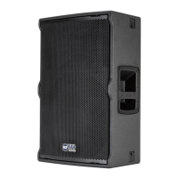
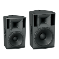
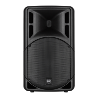
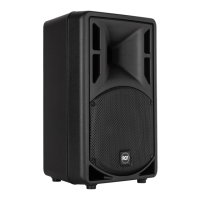
CABINETS
TT+ Series constant directivity horns are moulded in pure thick aluminium for improved heat-sink. The shape of the
horns is a unique design able to provide exceptional constant directivity.
All cabinets are in Baltic birch, heavy duty painted. Steel metal grilles are heavily powder coated.
Each cabinet is equipped with recessed side handles, fly tracks and threaded inserts for fixed installation.
REAR PANEL CONNECTIONS
WARNING: To prevent the risk of electric shock, do not connect the speaker with the amplifier switched on.
Before using the speaker, check to make sure that all the connections have been made correctly, to prevent
accidental short circuits from giving rise to electric sparks.
1. INPUT is a Neutrik NL4F Speakon connector for connecting a speaker-level signal.
2. OUTPUT is a Neutrik NL4F Speakon connector that is paralleled with the INPUT for daisy-chaining
speakers.
FULL RANGE MODE CONNECTION
The Speakon connectors use the following wiring standard:
Pin 1+ = Signal (+)
Pin 1– = Ground (–)
BI-AMP MODE CONNECTION
Pin 1+ = LF Signal (+)
Pin 1– = LF Ground (–)
Pin 2+ = HF Signal (+)
Pin 2– = HF Ground (–)
Pin 1+/1- input is directly connected to the woofer, Pin 2+/2- input is connected to the Compression Driver through
the MOSFET High Frequency Protection.
INSTALLATION
A 35 MM socket for mounting the loudspeaker on a speaker stand is provided in the bottom of the cabinet. Always
make sure that the pole mount that is used is able to sustain the speaker weight with a proper safety factor.
TT+ speakers MUST be suspended only with approved rigging hardware. In any case always use at least 2 fly-
track inserts.
TT22 and TT25 are equipped with 6 fly-tracks inserts. The inserts can be used in the following ways:
- single 3 points vertical installation
- single 3 points horizontal installation
- multiple 3 points vertical installation (max 3 in case of daisy chain)
- multiple 3 points horizontal installation (max 3 in case of daisy chain)
WARNING: In case of permanent installation always plan and execute specific inspections to verify all the parts
which must guarantee the security of the system / installation over time (brackets, screw anchors, screws, cabinets,
etc.).
WARNING: Never suspend in DAISY CHAIN MODE more than 3 (three) cabinets.
WARNING: Never suspend TT+ speakers by there handles. Handles are intended for transportation, not for
rigging.