Figures 10, 11, 12, 13 and 14 on pages 45, 46 and
47 show the possible connections of the “OUTPUT”
speaker terminals. To access the terminals, remove
the protective cover by unscrewing the 2 screws on
the top. Make the connections keeping in mind the
following indications.
Constant impedance lines
– The total impedance of the speakers connected
must correspond to the impedance selected on the
amplifier output terminals (4 Ω , 8 Ω ).
– The sum of the speaker power values must not be
less than the output power of the amplifier.
– The length of the connection cables must be
reduced to the minimum; in any case, the greater the
distance to be covered, the greater the cable cross-
section must be.
Constant voltage lines
– Each speaker must be equipped with a line
transformer having an input voltage equal to the
value selected on the output terminals of the
amplifier (50 V, 70 V, 100 V).
– The sum of the speaker power values must not
be greater than the output power of the amplifier.
A CLOSER LOOK: To guarantee correct
musical reproduction, a "phase"
connection should be made, in which the
terminal marked “0” of the amplifier
speaker terminals must correspond with the input
terminal marked “0” of the speakers (normally
marked in black).
Multiple speakers may be connected to the
constant impedance outputs in series or in parallel,
but the total impedance must in any case be equal to
or greater than the impedance value selected on the
amplifier output terminals.
When loads with greater impedance are connected
to the constant impedance outputs, the output power
is reduced.
15
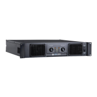
Protection devices
The UP power amplifiers incorporate a complete
range of protection devices to ensure the maximum
reliability. When one of these devices is tripped,
amplifier operation is interrupted and the
“OVERLOAD” LED and the LED corresponding to the
type of fault light up on the front panel. The
protection function intervenes in the following cases.
Overload on the amplifier.
Short circuit between the output terminals of the
amplifier.
Overheating of the final stages.
Excessively high input signal.
Breakage of the cooling fan.
VERY IMPORTANT: When the amplifier is
driving constant voltage lines (50 V, 70 V,
100 V), an overload may occur if the total
power of the speakers exceeds the amplifier output
power.
When the amplifier is driving constant impedance
lines (4 or 8 Ω ), an overload may occur if the total
impedance of the speakers is less than the
impedance selected on the output terminal strip.
If the amplifier stops working suddenly, switch it
off and let it cool. After checking the speaker line to
remove any possible faults, try switching the
amplifier on again. If it does not begin operating,
contact your RCF S.p.A. SERVICE CENTRE.