EasyManua.ls Logo

RCT MUIRHEAD - User Manual

Default Icon
12 pages
Print Icon
To Next Page IconTo Next Page
Loading...
PRODUCT MANUAL
OVERCRANK PROTECTION CONTROLLER
Part No. 11966 | 12725 | 12726
Question and Answer IconNeed help?

Do you have a question about the RCT MUIRHEAD and is the answer not in the manual?

Summary

General Safety Warnings

Personal Safety

Ensures personnel are trained, authorized, and follow site-specific safety procedures.

Machine Safety

Adheres to OEM procedures for pre-start checks, isolation, and safe operation.

Product Safety

Emphasizes reading instructions, correct connections, and observing all warnings.

Product Overview

Features and Functions

Highlights multi-voltage, IP65 rating, overcrank protection, and robust design.

Operation and Use

Controller Status Indicators

Explains indicator sequences for power-up, faults, system status, and input activity.

Installation Guide

Wiring Connections

Details terminal connections, wire colours, functions, and descriptions for proper installation.

External Wiring Diagram

Calibration

Service Information

Details recommended service schedule and procedures for inspection and testing.

Parts List (12 V Kit)

Lists components and suggested spares for the 12V Overcrank Controller Kit.

Technical Specifications

Compliance and Standards

Lists relevant regulations like ACMA, EU, FCC, and IC that the product complies with.

Troubleshooting

Troubleshooting Common Faults

Identifies common faults and their possible causes, focusing on wiring and connections.

Glossary

Defines technical abbreviations and terms used throughout the manual.

Warranty

Provides information on the product's warranty and where to find further details.

Overview

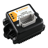
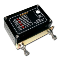
The Muirhead Overcrank Protection Controller, part number 11966 (also available as kits 12725 for 24V and 12726 for 12V systems), is a robust and compact device designed to safeguard engine starter motors from damage caused by excessive cranking. Manufactured by Remote Control Technologies (RCT), this controller is an integral part of their "Smart Protection Systems."

Function Description:

The primary function of the Overcrank Protection Controller is to prevent over-cranking of an engine's starter motor. It achieves this by monitoring the duration of the cranking event and automatically stopping the starter motor if the cranking time exceeds a predefined limit. This mechanism is crucial for extending the lifespan of starter motors and associated electrical components, which can be subjected to significant wear and heat build-up during prolonged cranking attempts.

The controller incorporates a "crank time period" setting, which defines the initial duration the engine can be cranked without triggering a lockout. The default for this is 10 seconds, adjustable between 5 and 12 seconds. If the cranking continues beyond this initial period, the controller enters a "lockout period" to allow the starter motor to cool down. The default lockout period is 60 seconds, adjustable between 30 seconds and two minutes. During this lockout, an external LED indicator, typically mounted in the instrument panel, illuminates to inform the operator that the start circuit is temporarily disabled.

Additionally, the device features a "max crank time period," which is the absolute maximum allowable time for the engine to be cranked at any point. The default for this is 30 seconds, adjustable between 15 and 30 seconds. This ensures that even with repeated short cranking attempts, the total cranking time does not exceed a safe limit.

A key operational feature is the bypass switch functionality. This allows maintenance personnel to temporarily override the overcrank protection, enabling them to crank the vehicle for as long as necessary without interruption. This is particularly useful during diagnostic or repair procedures where extended cranking might be required.

The controller's status is communicated through a series of indicator lights:

  • Battery Power-up: All indicators turn on, then off, before the controller reverts to normal operation.
  • Red (Alarm Indication): Indicates a fault, such as problems with outputs (over current on high current outputs 1 & 2, incorrect voltage on output 4), or if the board temperature exceeds 80 °C.
  • Yellow (Power Indication): Pulses during normal operation, signifying system OK. It also flashes on and off at one-second intervals during a lockout period.
  • Green (System Status): On for normal operation. It flashes when a valid input goes active, with the number of flashes corresponding to the input number, allowing verification of correct wiring and input toggling.

Important Technical Specifications:

  • Multi-voltage: Operates on 12-24 V DC systems.
  • Input Nominal Voltage: 12 to 24 V DC.
  • Min and Max Input Voltage: 9 to 35 V DC.
  • Ignition Output Rated Continuous Current: 10 A.
  • Dimensions (controller only): Length: 119 mm | Width: 80 mm | Height/Depth: 65 mm.
  • Weight (controller only): 255 g.
  • Connection Types: 12-pin receptacle.
  • Inputs: Ignition supply, bypass input, battery supply, chassis ground.
  • Circuit Protection: External control.
  • Enclosure Type: ABS.
  • Environmental Protection IP Rating: IP65, indicating it is environmentally sealed and protected against dust and water ingress.
  • Compliance and Standards: Complies with ACMA (IEC 61000-6-1:2005, IEC 61000-6-3:2006, A1:2010), EU (RoHS 2 Directive 2011/65/EU), FCC (exempt from 47 CFR 15.103), and IC (exempt from ICES-003).

Usage Features:

  • Overcrank Visual Warning: An external LED provides a clear visual indication to the operator when the overcrank protection is active or in a lockout state.
  • Adjustable Timings: The crank time period, max crank time period, and lockout time period are adjustable, allowing customization to suit different engine types and operational requirements. These parameters can be changed through programming using a utility available from RCT.
  • Bypass Functionality: A dedicated bypass switch allows maintenance staff to temporarily disable the overcrank protection for specific tasks.
  • Compact and Robust Design: The controller's small footprint and durable, IP65-rated enclosure make it suitable for harsh industrial environments.
  • Easy Installation: The manual provides clear instructions for installation, including wiring connections and a detailed wiring diagram (501d). It emphasizes the critical need for a relay in the system as a fail-to-safe circuit to prevent engine or component damage.

Maintenance Features:

  • Service Schedule: RCT recommends performing a visual inspection and system test at each machine's scheduled service interval.
  • Visual Inspection: Includes checking the controller, wiring connections, looms, and switches for any signs of damage or wear.
  • System Test: Involves operating the machine as per the "Operation and Use" section of the manual to verify the controller's functionality.
  • No User-Serviceable Parts: The equipment contains no internal user-serviceable parts. In case of internal issues, the unit must be returned to RCT for repairs.
  • Calibration: The manual details the default and adjustable settings for crank time, max crank time, and lockout time, providing guidance for calibration. Access to a programmable controller utility from RCT is required for changing these parameters.

The Muirhead Overcrank Protection Controller is a vital component for any machine where starter motor longevity and reliable engine starting are critical, offering intelligent protection and clear operational feedback.

RCT MUIRHEAD Specifications

General IconGeneral
BrandRCT
ModelMUIRHEAD
CategoryController
LanguageEnglish

Related product manuals