ADJUSTMENT
CONNECTION
REPAIR
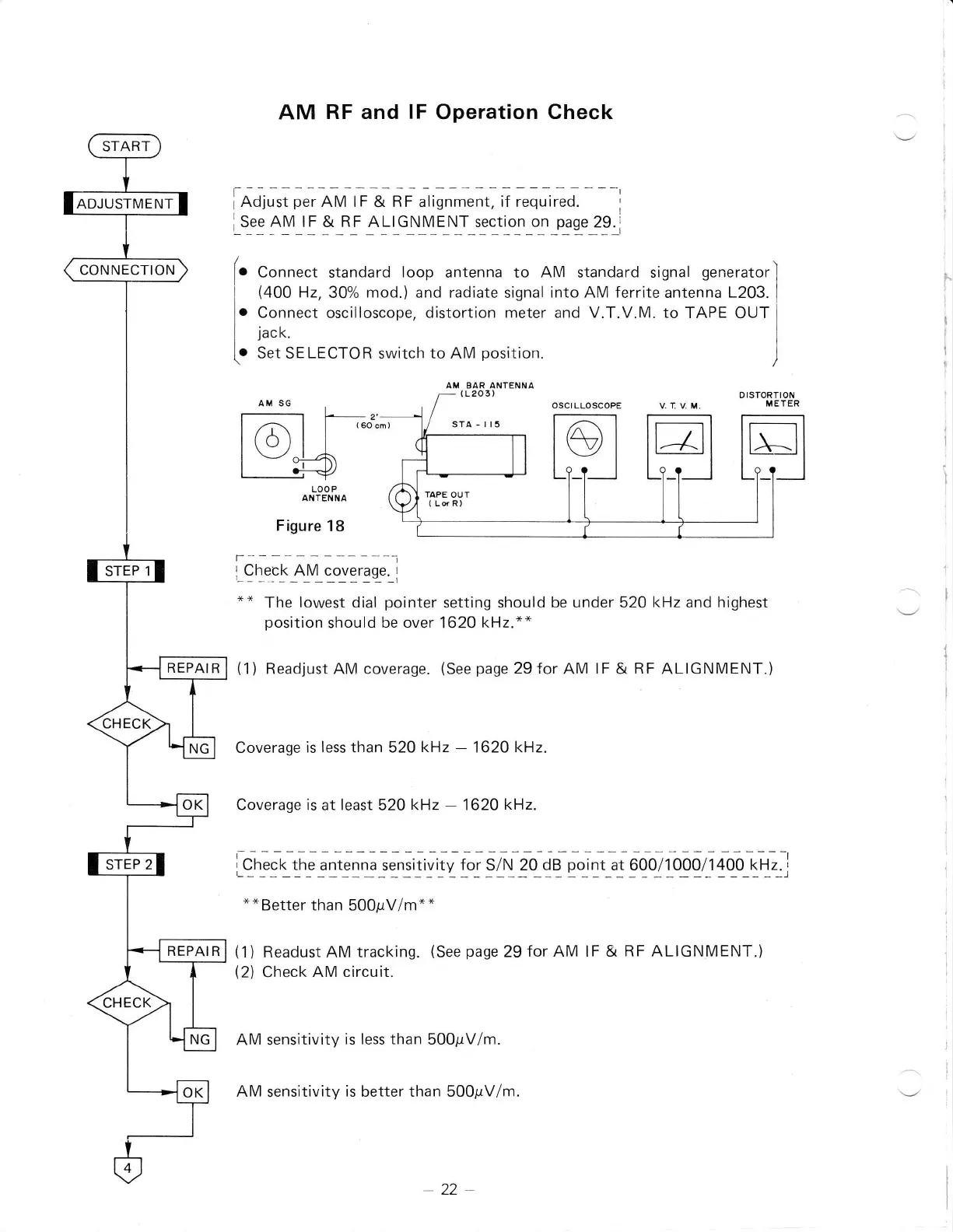
AM
RF and lF
Operation
Check
[na;"J;.r
AM G
&
RF
atisnment,
ir requ-t[0.-
--i
i_s_eg4y_t59
jI4_Llclyrli[_s3c_t1o1_ol_p_uq"_29_l
[.
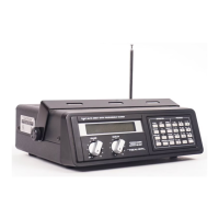
Conn.", standard loop antenna to AM standard signal
generatorl
I
(400
Hz,
30%
mod.)
and radiate signal
into AM ferrite
antenna
L203.
I
i.
Connect osciiloscope, distortion
meter and V.T.V.M.
to TAPE
OUT;
I
jact.
I
[.
S". SE
LECTOR
switch to AM
position.
)
l_ 2'
lr$ I |
(6oc
L:i$
LOOP
ANTENNA
Figure
18
r---
-----t
l_9
tql!
3lL
c_9y
9
r9
s_e
: I
"*
The
lowest dial
pointer
setting should
be under 520
kHz
and highest
position
should
be over
1620
kHz.*"
(1)
Readjust AM coverage.
(See
page
29
for AM lF &
RF
ALIGNMENT.)
Coverage
is less than 520
kHz
-
1620 kHz.
Coverage is
at
least
52A
k1z
-
1620
kHz.
i_.lSg*!f
Sl;;J9,:r!r1,'_tv1"1_sl*_rga_q.f 1i_liooorlogqrrlootH,-.,
"*Better
than 500pV/m*"
(1)
Readust AM tracking.
(See
page
29
for AM lF & RF ALIGNMENT.)
(2)
Check AM
circuit.
AM sensitivity
is less
than
500pV/m.
AM
sensitivity
is better than 500pV/m.
-22