Do you have a question about the Realistic STA-235B and is the answer not in the manual?
Information on this addendum covering changes for the STA-235B.
Compares FM output voltage between STA-235 and STA-235B.
Diagram illustrating the receiver's internal signal paths.
Procedure for FM RF and IF alignment for the STA-235B.
Setup and connection guide for MPX alignment.
Visual guide to alignment adjustment points on circuit boards.
Common FM problems, their causes, and remedies.
Solutions for poor stereo separation and low FM volume.
Component layout for the tuner board top side.
Component layout for the tuner board bottom side.
Component layout for the main amplifier board top side.
Component layout for the main amplifier board bottom side.
Component layout for the tone amp and auto-muting board top side.
Component layout for the tone amp and auto-muting board bottom side.
Detailed list of passive and semiconductor components.
List of integrated circuits, resistors, transistors, and lamps.
Lists for variable parts, switches, and miscellaneous items.
The document you provided is an addendum to the service manual for the Realistic STA-235B AM/FM Stereo Receiver, catalog number 31-2065. This addendum specifically covers the changes made for the "B" version of the STA-235, and it emphasizes that for complete coverage of this model, both this addendum and the original service manual for the STA-235 must be consulted.
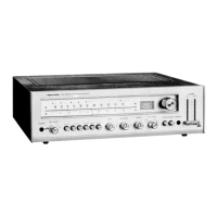
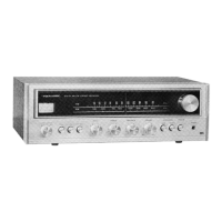
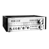
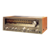
The Realistic STA-235B is an AM/FM stereo receiver, a central component in a home audio system designed to receive radio broadcasts and amplify audio signals from various sources for playback through speakers. As a stereo receiver, it integrates several key functions into one unit: a tuner for radio reception, a preamplifier for signal processing and control, and a power amplifier for driving loudspeakers.
The core function of the STA-235B is to provide high-quality audio reproduction from both radio broadcasts and external audio sources. The AM/FM tuner section allows users to receive both Amplitude Modulation (AM) and Frequency Modulation (FM) radio signals. The FM section is particularly designed for stereo broadcasts, offering a richer and more immersive listening experience. The receiver also includes inputs for external audio components, such as a turntable (phono input), auxiliary devices (AUX), and tape decks (Tape 1 In, Tape 2 In). This versatility allows the STA-235B to serve as the hub for a complete home entertainment system, enabling users to switch between different audio sources seamlessly.
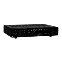
The preamplifier section handles signal routing and tone control. It allows users to adjust the bass, midrange, and treble frequencies to tailor the sound to their preferences or the acoustics of their listening environment. A volume control is, of course, a fundamental feature, enabling precise adjustment of the overall output level. The power amplifier section takes the processed audio signals and amplifies them to a level sufficient to drive passive loudspeakers, delivering the sound to the listener. The receiver supports connecting multiple pairs of speakers, typically labeled A and B, allowing for flexible speaker setups, such as powering speakers in different rooms or using two pairs in a single room.
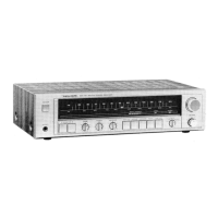
The STA-235B offers a range of features designed to enhance the user's listening experience and provide control over the audio output. The front panel, as depicted in the image, includes a tuning knob for precise selection of radio stations, along with a dial scale that visually indicates the selected frequency for both AM and FM bands. A signal meter is present, which helps in accurately tuning into radio stations by indicating signal strength. For FM stereo broadcasts, a stereo indicator light illuminates when a strong stereo signal is received, confirming the stereo reception mode.
The receiver incorporates several audio enhancement and control switches. A "Loudness" switch is typically included to compensate for the human ear's reduced sensitivity to bass and treble frequencies at low listening volumes, providing a fuller sound even when the volume is turned down. "Mono" and "FM 25µS" switches suggest options for managing FM reception, with "Mono" forcing monaural reception, which can improve signal clarity in weak stereo signal conditions, and "FM 25µS" likely referring to a de-emphasis setting for specific broadcast standards. Filter switches, such as "Hi Fil" (High Filter) and "Lo Fil" (Low Filter), are available to reduce unwanted noise or hiss in the high frequencies and rumble or hum in the low frequencies, respectively, which can be particularly useful when listening to older recordings or broadcasts.
For recording purposes, the STA-235B provides "Tape Monitor" and "Dub Out" functions. The "Tape Monitor" allows users to listen to the signal directly from a connected tape deck during recording, enabling real-time monitoring of the recording quality. The "Dub Out" feature facilitates copying audio from one tape deck to another, or from any other source to a recording device, offering flexibility for audio archiving or sharing. Headphone jacks are also a standard feature, allowing for private listening without disturbing others.
The addendum itself is a key aspect of the maintenance features, as it provides updated information for servicing the "B" version of the STA-235. This indicates a commitment to supporting the product throughout its lifecycle, even with minor revisions. The document includes a detailed "Contents" section, outlining various aspects crucial for maintenance and repair.
The "Specifications" section, while not to be detailed here, is essential for technicians to verify the device's performance against factory standards. The "Block Diagram" provides an overview of the receiver's internal architecture, illustrating the signal path and the interconnections between different functional blocks. This is invaluable for troubleshooting, as it helps technicians isolate problems to specific sections of the circuit.
"Alignment Procedure" and "Alignment Points" are critical for ensuring the receiver's optimal performance, especially for the tuner section. These sections detail the steps and locations for adjusting various components (e.g., coils, potentiometers) to achieve the correct frequency response, sensitivity, and stereo separation. The addendum specifically highlights changes in alignment points for the FM RF and IF alignment, as well as MPX alignment, between the STA-235 and STA-235B models, underscoring the importance of referring to the correct documentation for each version.
The "Troubleshooting" section is a practical guide for diagnosing common issues. It lists symptoms (e.g., "FM does not operate," "Poor multiplex separation," "Stereo indicator does not light," "FM volume not sufficient") and provides corresponding causes and remedies. This section directs technicians to specific components or integrated circuits that might be defective, offering guidance on replacement. For instance, it mentions checking for defective ICs (IC201, IC301), transistors (TR101, TR102, TR103, TR301, TR302), resistors (R201-R206, R208, R209, R213, R219, R220, R321), capacitors (C112, C201, C203, C227, C301), coils (L101-L104), and filters (LPF301, LPF302). The addendum also indicates that certain troubleshooting items from the original manual should be deleted, further emphasizing the specific nature of the "B" version's service information.
Detailed "Tuner Board 0042 (Top View)" and "Main Amp Board 0045 (Top View/Bottom View)" diagrams are provided, showing the physical layout of components on the printed circuit boards. These visual aids are indispensable for locating specific parts during repair. Similarly, the "Tone Amp & Auto-M Board 0043" diagrams offer detailed views of another critical board.
Finally, comprehensive "Electrical Parts List," "Miscellaneous Parts List," and "Schematic Diagram" sections (the schematic diagram being a separate sheet) are included. The parts lists provide reference numbers, values, voltages, tolerances, and material types for capacitors, resistors, diodes, coils, transformers, integrated circuits, lamps, light-emitting diodes, meters, relays, switches, and thermistors. This information is crucial for ordering replacement parts and ensuring that the correct components are used for repairs, maintaining the original performance characteristics of the receiver. The inclusion of manufacturer part numbers and substitute options further aids in sourcing components.
In summary, the Realistic STA-235B AM/FM Stereo Receiver is a versatile audio component designed for radio reception and amplification of various audio sources. Its usage features focus on user control over tuning, sound characteristics, and recording capabilities, while its comprehensive service manual addendum provides detailed information and visual aids essential for effective maintenance and repair.
| Frequency Response | 20 Hz to 20 kHz |
|---|---|
| Total Harmonic Distortion (THD) | 0.5% |
| Speaker Impedance | 4 to 16 ohms |
| Input Sensitivity | 2.5mV (phono), 150mV (line) |
| Signal-to-Noise Ratio | 70 dB |
| Tuning Range | FM |
| Output | Headphones |