Do you have a question about the Realistic STA-7 and is the answer not in the manual?
Performance metrics and limits for the AM broadcast band reception.
Performance metrics and limits for the FM broadcast band reception.
Performance metrics for FM stereo and multiplex signal processing.
Procedure to verify the functionality and output voltages of the power supply.
Steps to test the operation of the main amplifier and pre-amplifier circuits.
Procedures and settings for aligning the AM receiver's intermediate and radio frequency stages.
Procedures and settings for aligning the FM receiver's radio frequency and intermediate frequency stages.
Procedures for aligning the FM stereo decoder and multiplex circuits.
Description of the circuit that limits output current to protect the IC.
Explanation of the circuit that reduces output when the chip overheats.
Description of the circuit designed to prevent noise during power transitions.
Addresses common problems like no output, pilot lamp failures, fuse issues, and speaker problems.
Guidance on adjusting R167 to control FM stereo indicator sensitivity.
List of capacitors used in the unit, including values and types.
List of diodes, filters, fuses, integrated circuits, jumper wires, and lamps.
List of resistors used in the unit, including values and wattage.
List of switches, transistors, and variable components used in the unit.
Detailed internal schematic of the HA-1370 integrated circuit.
Detailed internal schematic of the LA-3350 integrated circuit.
| Brand | Realistic |
|---|---|
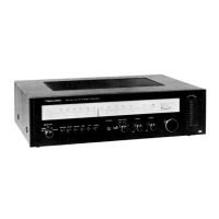
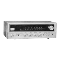
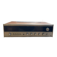
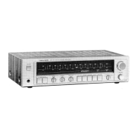
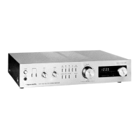
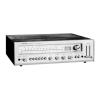
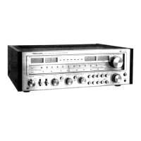
| Model | STA-7 |
| Category | Stereo Receiver |
| Language | English |