SYMPTOM
CAUSE,,
REMEDY
2)
ln case
of
FM
reception, VR202, D206,
C243, C244 or
R24O
defective
Replace
the
defective
part(s).
3)
ln
case of AM reception,
VR201,
D2O4,
R242
or C237-239
defective
Replace
the defective
part(s).
4) Defective
1C201
Replace
the
lC.
8.
BRIEF DESCRIPTION
OF
PROTECTOR CIRCUIT
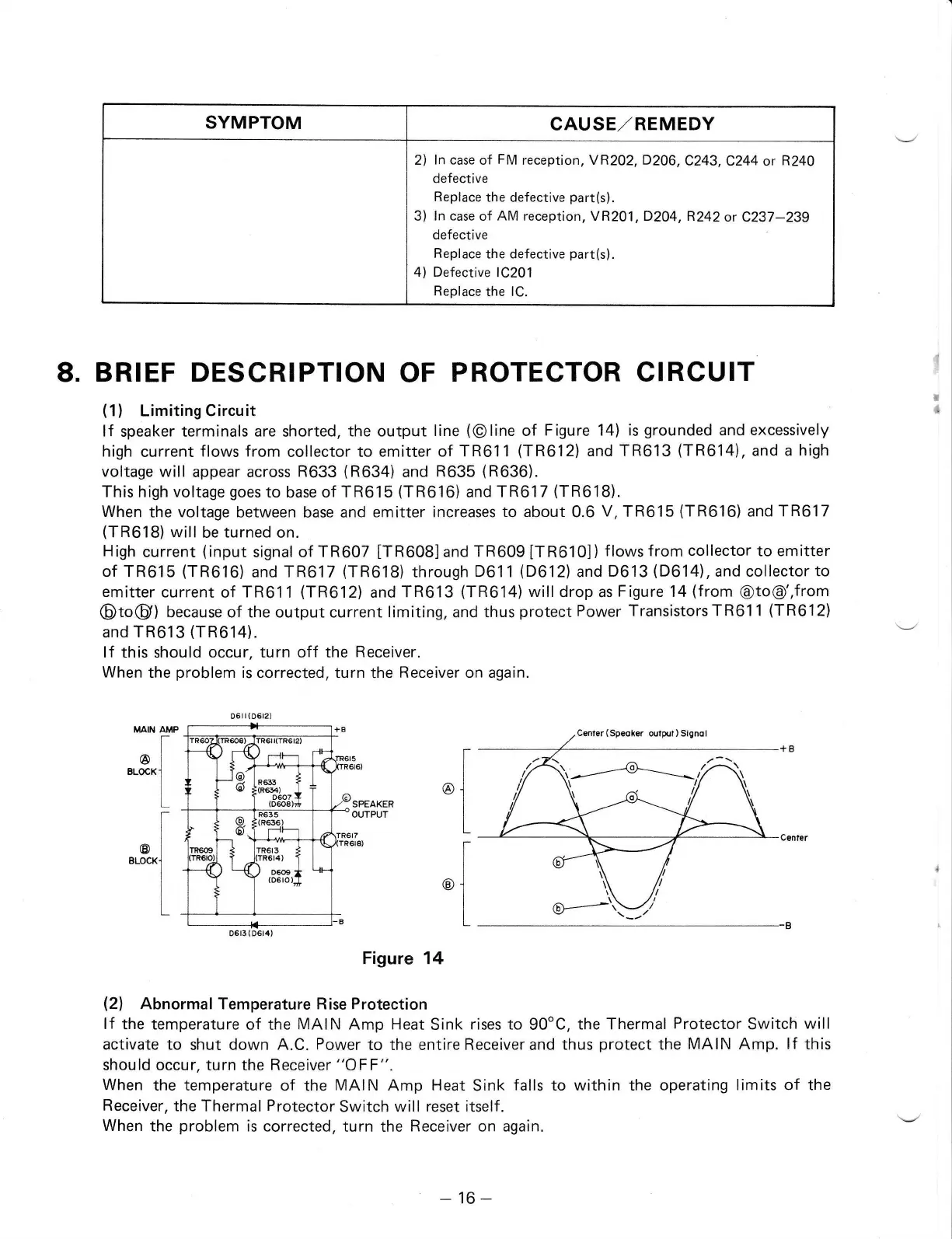
(1)
Limiting Circuit
lf
speaker terminals are shorted,
the output
line
(@line
of
Figure 14) is
grounded
and
excessively
high
current
flows from
collector to emitter
of TR611
(TR612)
and TR613
(TR614),
and
a
high
voltage will
appear across
R633
(R634)
and
R635
(R636).
This
high voltage
goes
to
base
of TR615
(TR616)
and
TR617
(TR618).
When
the voltage
between base and
emitter increases
to about
0.6
V, TR615
(TR616)
and
TR617
(TR618)
will
be
turned
on.
High
current
(input
signal of
TR607
[TR608]and
TR609
[TR610])
f
lows
from
collector
to emitter
of TR615
(TR616)
and
TR617
(TR618)
through
D611
(D612)
and
D613
(D614),
and collector
to
emitter
current of
TR611
(TR612)
and
TR613
(TR614)
willdrop
as
Figure 14
(from
@to@',from
@to@)
because of the output current limiting, and thus
protect
Power
Transistors TR611
(TR612)
and
TR613
(TR614).
lf this should occur, turn off
the Receiver.
When
the
problem
is
corrected, turn the
Receiver on again.
Figure 14
(21
Abnormal Temperature Rise Protection
lf
the temperature
of the
MAIN Amp Heat
Sink
rises to
90oC,
the Thermal
Protector
Switch
will
activate to
shut down A.C.
Power
to the entireReceiverand thus
protect
the
MAIN Amp.
lf
this
should occur, turn the
Receiver
"OFF".
When
the temperature
of the
MAIN
Amp
Heat
Sink
falls
to within the operating
limits of the
Receiver,
the Thermal
Protector
Switch will
reset itself.
When
the
problem
is
corrected, turn the
Receiver
on again.
SPEAKER
OUTPUT
^[
**-L
,I
erccxl
I
,l
'l
06il(0612)
tB6tI I RSta
l-*-
*
R6B *
'"q;L,{
\
@
!@.
i6
E'
)L(
R655
(R636
)
-Fr
6
rn6rs +
:rR6r4)
I
)
o"o"
rl
(06ro)J
\
{F
B
D6t3(D6t4)
-16-