13
10. Basic Operation - cont.
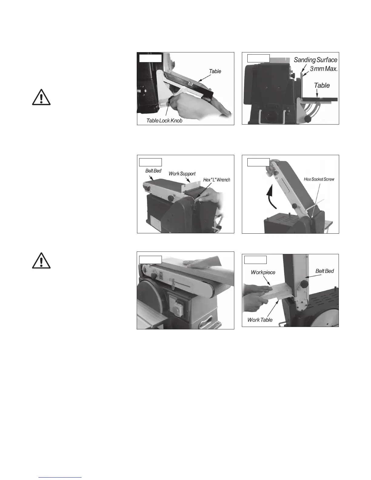
Bevel Sanding
The work table can be tilted from 0º to 45º for
bevel sanding. Loosen the table lock knob and
tilt the worktable to desired angle as shown,
Fig 10.1. Re-tighten table lock knob.
Warning: To avoid trapping the work or
fingers between the table and sanding
surface, the table should repositioned on
the table support to retain a maximum of
3 mm distance between sanding surface
and table, Fig 10.2.
Positioning the Belt Bed
A bed locking hex socket head screw locks the
belt bed in a vertical or horizontal position. To
adjust the vertical position:
1. Loosen the hex socket head locking screw
using a 6 mm hex wrench, Fig 10.3.
2. Position belt bed vertically as shown in Fig
10.4 and tighten the hex socket head
locking screw.
Surface Sanding On The Belt
Warning: To avoid injury from slips,
jams or thrown pieces, adjust the work
support to clear the sanding surface by
no more than 3 mm.
When checking clearance between the belt and
work support, press the belt flat against the
metal beneath it.
Hold the workpiece firmly with both hands,
keeping fingers away from the sanding belt, Fig
10.5.
Keep the end butted against the backstop and
move the work evenly across the sanding belt.
Use extra caution when sanding very thin pieces.
For sanding long pieces, remove the
work support.
Apply only enough pressure to allow the sanding
belt to remove material.
Fig 10.1
Fig 10.3
Fig 10.5
End Sanding On The Belt
It is more convenient to sand the ends of long
workpieces with the sanding belt in a
vertical position.
If necessary, install the worktable assembly.
Move the work evenly across the sanding belt,
Fig 10.6.
Fig 10.6
Fig 10.2
Fig 10.4