8
7. Assembly Instructions
Mounting Belt and Disc Sander to Workbench
If belt and disc sander is to be used in a permanent location, it should be
fastened securely to a firm supporting surface such as workbench.
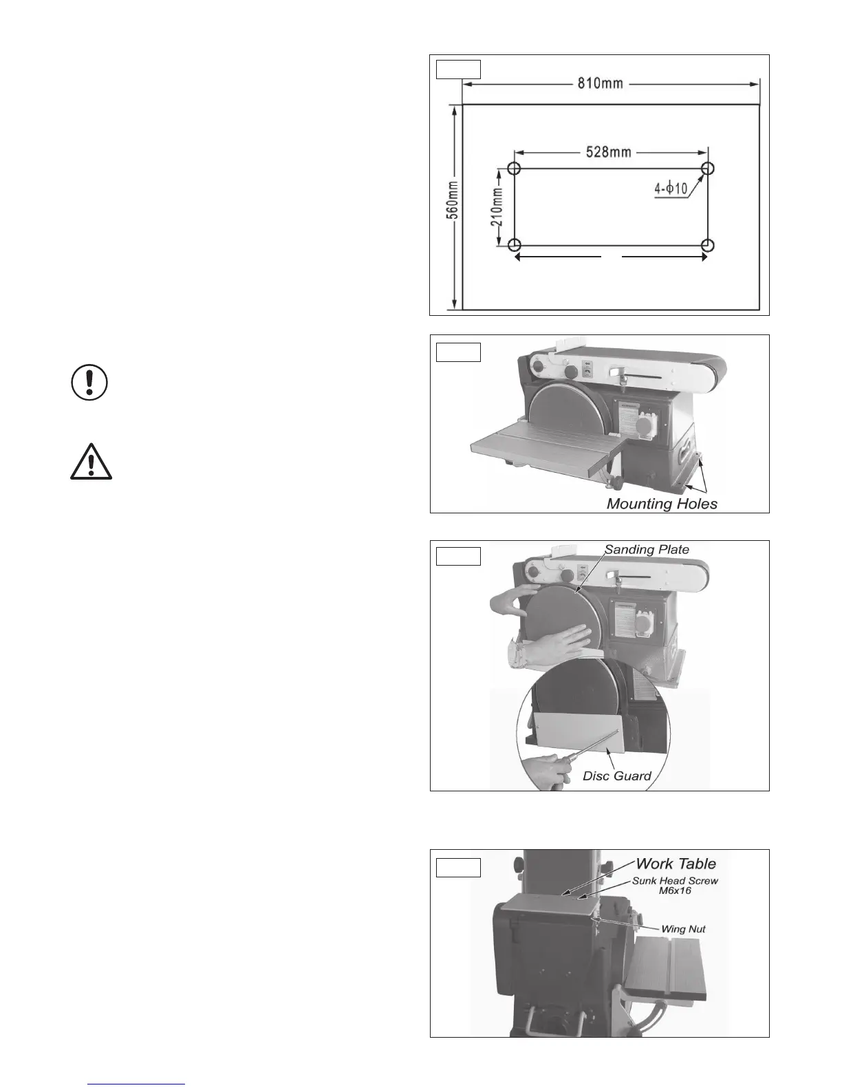
If mounting to a workbench, holes should be drilled through supporting
surface of the workbench using dimensions shown in Fig 7.1.
1. The unit should be bolted securely using M8 screws and hex nuts (not
included). The screw length should be 50 mm plus the thickness of the
bench top.
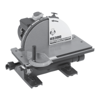
2. Locate the mounting holes, Fig 7.2, and mark the holes through
the workbench.
3. Drill 4-10 mm diameter holes through workbench.
4. Place belt and disc sander on workbench aligning holes on base with
holes drilled in workbench.
5. Insert 4 M8 screws and tighten hex nuts.
NOTE: The mounting holes marked (A) Fig 7.1 should be a maximum of
140 mm from the front edge of the work bench.
Caution: To avoid injury from tool movement, the supporting
surface where the belt and disc sander is mounted should be
examined carefully after mounting to ensure that no movement
during use can result. If any movement occurs, secure the
workbench or supporting surface before resuming operation of
the belt and disc sander.
Installing Sander Disc and Guard
1. Remove the backing from the self-adhesive sanding disc. Align perimeter
of disc with plate and press disc firmly into position all the way around,
Fig 7.3.
2. Locate disc guard and two pan head screws M4 x 40, from the loose
parts bag.
3. Position disc guard against lower 1/3 disc aligning holes, Fig 7.3.
4. Using a Phillips screwdriver, fasten the pan head screw securely applying
slight pressure to thread the holes.
Installing Work Table
1. Place the work table for the belt on the work support.
2. Insert 2 counter sunk head screws through the work table and the work
support slot, Fig 7.4.
3. Put a 6 mm washer and a wing nut on the screw and tighten.
If mounting the machine to the optional floor stand,
Please refer to section 17.