EasyManua.ls Logo

Rectifier MCSU-4 - Page 17

Default Icon
86 pages
Print Icon
To Next Page IconTo Next Page
To Previous Page IconTo Previous Page
Loading...
Installation, Operation and Technical Manual Rectifier Technologies
158-1872-01 13 19-Feb-14
Figure 4.2 Battery transducers connection to MUIB
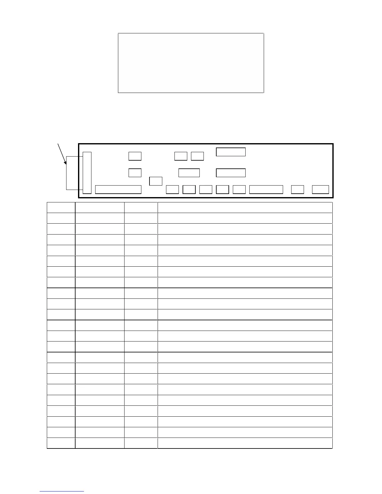
Figure 4.3 MUIB Connection Diagram
X1
X2
X18
X17
X28
X31
X32
X22
X23
X33
X34
X44
X45
X39
X40
34-way ribbon
cable to MiniCSU
X50
X64
X65
Conn #
Conn Label
Class
Used for:
X1
MiniCSU
Anal/Dig
34-way ribbon cable to MiniCSU
X2
RELAY 1
Digital
Dummy load on 110V systems, not used on other systems
RELAY 2
Cabinet Fan control for RT4 or RT5 systems
RELAY 3
SMR HVSD Alarm
RELAY 4
Activated by any alarm condition
RELAY 5
SMR switched off (for any reason)
X17
BAT. TEMP.
Analog
Temperature Transducer
X18
AMB. TEMP.
Analog
Temperature Transducer
X22
C.B. TRIP
Digital
Aux contact from load CBs
X32
1 PHASE AC
Anal/Dig
Not used with MCSU-4
X23
BAT. SW.
Digital
Aux contact from Batt. CBs
X33
USER 1
Digital
User defined i/p; isolated aux. Contact or similar
X34
USER 2
Digital
Requires special software to define function
X44
USER 3
Digital
“ “
X45
USER 4
Digital
“ “
X28
AN 1
Analog
Spare analog I/P - 0 to 5VDC (Requires special software)
X31
AN 2
Analog
Spare analog I/P - 0 to 5VDC (Requires special software)
X39
BATTERY 1
Analog
Battery current transducer
X40
BATTERY 2
Analog
Battery current transducer
X50
POWER I/P
Analog
System voltage sensing and DC power input for MiniCSU
X64
LVDS Aux
Digital
Aux contact from LVDS contactor
X65
LVDS Coil
Digital
Drive for contactor or similar

Table of Contents

Related product manuals