Installation, Operation and Technical Manual Rectifier Technologies
158-1872-01 33 19-Feb-14
4.9.2 BCM Specifications
Battery configuration options:
24Cell x 2V, 12Cell x 4V,
8Cell x 6V, 4Cell x 12V
12Cell x 2V, 6Cell x 4V,
4Cell x 6V, 2Cells x 12V
(DIP switch setting on the board):
Note: “Cell” can mean both single battery cell or monoblock.
5mV per cell (2V, 4V, 6V range),
10mV per cell (12V range)
Sampling interval range for
discharge log:
Power supply: from MCSU-4
Maximum distance from MCSU-4:
10m (of 16 way ribbon cable)
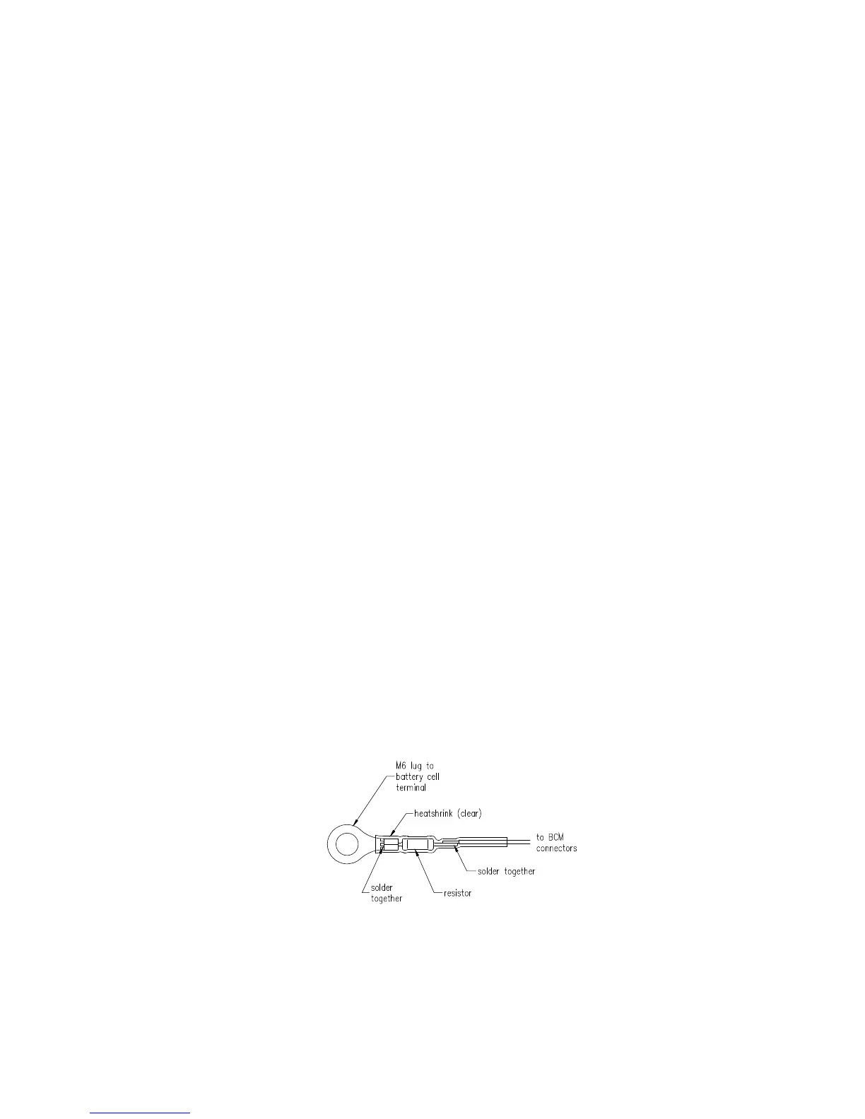
4.9.3 Preparing the battery for connection to the BCM
Battery cells are not connected to the BCM directly. 56/PR02 resistors are inserted
between BCM and the cells to clear any fault that would arise if a battery cell lead were
shorted. The resistors are mounted as near as possible to the battery terminal in order to
protect as much of the wiring as possible. A typical connection is shown Figure 4.9.
Figure 4.9 Lead termination at battery cell.
The M6 ring lug (depending on type of battery) is screwed onto the cell terminals. The
other end of the wire is screwed onto the 5.0mm pitch screw terminals. Details on how the
cells connect to the BCM board are discussed in later sections.