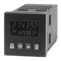
SW3 - HI BIAS: Sets input trigger levels at mid-range, to accept outputs from
2-wire proximity sensors, resistive photo-cells, and logic pulses
with full 0 to +12V swings.
Input trigger levels: V
IL
= 5.5 V max; V
IH
= 7.5 V min.
LO BIAS: Sets input trigger levels to low range, to accept logic pulses
with 0 to +5 V swings.
Input trigger levels: V
IL
= 1.5 V max; V
IH
= 3.75 V min.
Note: V
IL
and V
IH
levels given are typical values ±10%, when the counter
voltage at the DC OUT/IN terminal, is +12 VDC. These typical values will
vary in proportion to the variations in DC OUT/IN terminal voltage, caused
by line voltage and load changes.
INPUT B
SW4 - Same as SW1
SW5 - Same as SW2
SW6 - Same as SW3
SW7 - PGM.DIS.: See Front Panel Accessible
Functions With Program Disable,
page 14, for details.
-9-
7
9
TO PROCESSOR
Figure 9, Input Circuit Schematic
7654321
ON
SRC
LO FRQ
LO BIAS
SRC
LO FRQ
LO BIAS
PGM.DIS. ON
HI
HI
SNK
HI
HI
SNK
PGM.DIS. OFF
INPUT A
SET-UP SET-UP
INPUT B
Figure 8, DIP Switches
Note: Input B uses
DIP switches SW4,
SW5 and SW6.