4
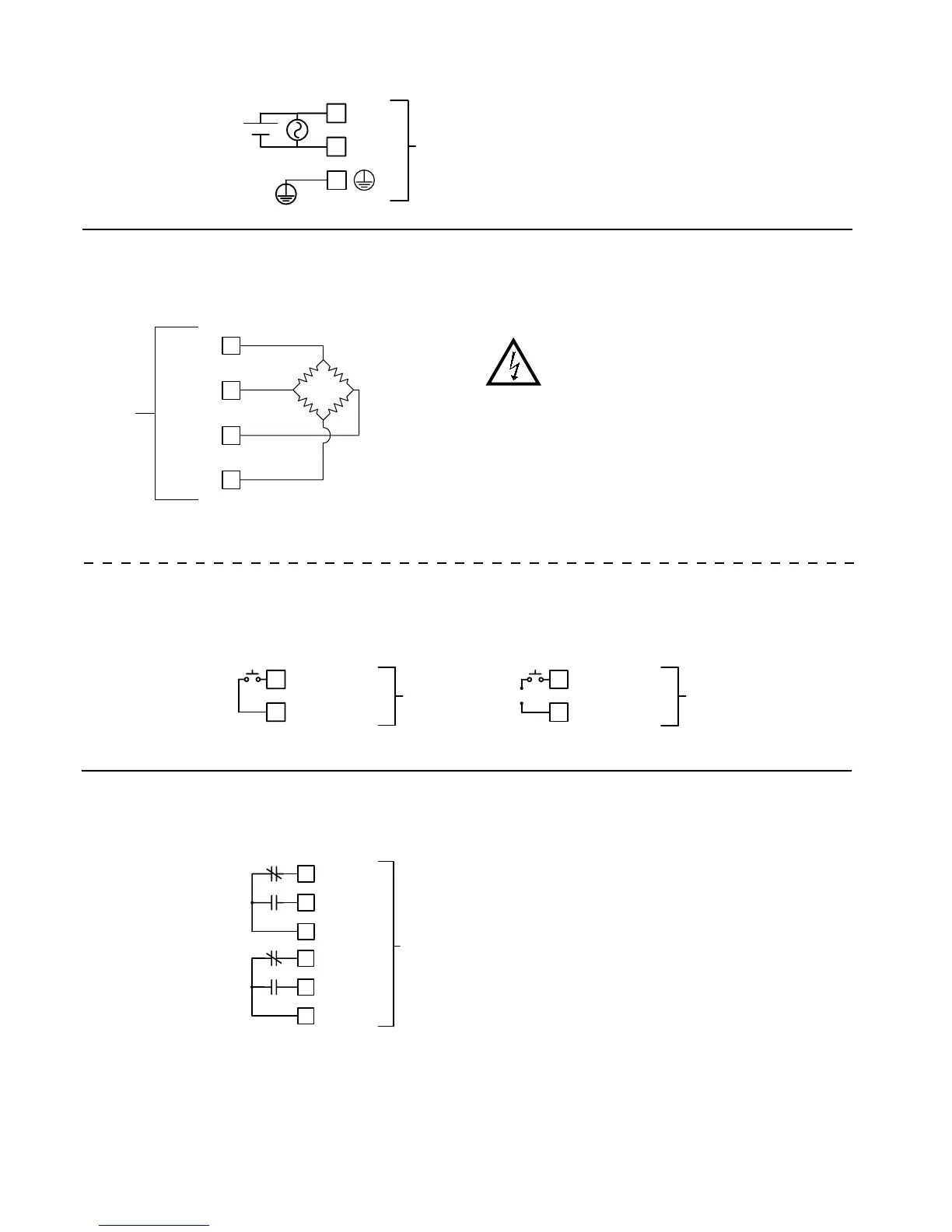
3.2 INPUT WIRING
USER INPUT WIRING
CAUTION: Analog common is NOT isolated from user input
common. In order to preserve the safety of the meter application,
the DC common must be suitably isolated from hazardous live
earth referenced voltage; or input common must be at protective
earth ground potential. If not, hazardous voltage may be present
at the User Input and Input Common terminals. Appropriate
considerations must then be given to the potential of the input
common with respect to earth ground. Always connect the
analog signal common to terminal 4 (-EXC).
The User Input is located: LD2 - left side, LD4 - right side
Terminal 1: User Comm
Terminal 2: User 1
Terminal 3: User 2
Terminal 4: User 3
3.3 SETPOINT (OUTPUT) WIRING
The setpoint relays use a six position terminal block (TBB) located inside the
(right side).
Terminal 1: NC 1
Terminal 2: NO 1
Terminal 3: Relay 1 Common
Terminal 4: NC 2
Terminal 5: NO 2
Terminal 6: Relay 2 Common
USER
*
USER COMM
1
TBD
USER
USER COMM
1
*
TBD
+
-
1
N.C. 1
COMM 1
3
2
N.O. 1
TBB
4
5
6
N.C. 2
N.O. 2
COMM 2
Sinking Logic
Sourcing Logic
2
1
4
3
+EXC
+IN
-IN
-EXC
TBC
EXC+
EXC-
SIG-
SIG+
Before connecting signal wires, the Range and Excitation Jumpers should be
verified for proper position.
* For single ended input, tie terminal 3 (-IN) to Terminal 4 (-EXC).
The power wiring is made via the 3 position terminal block (TBA) located inside the unit (right side).
3.1 POWER WIRING
Power
Terminal 1: VAC/DC +
Terminal 2: VAC/DC -
Terminal 3: Protective Conductor
Terminal
1
2
L(+)
N(-)
3
TBA
+
-

 Loading...