2
Max./Min. capture delay time: 0 to 3275 sec.
9. USER INPUTS: Three programmable user inputs
Max. Continuous Input: 30 VDC
Isolation To Sensor Input Common: Not isolated.
Response Time: 50 msec. max.
Logic State: Jumper selectable for sink/source logic
INPUT STATE
SINKING INPUTS
22 KΩ pull-up to +5 V
SOURCING INPUTS
22 KΩ pull-down
Active V
IN
< 0.9 VDC V
IN
> 3.6 VDC
Inactive V
IN
> 3.6 VDC V
IN
< 0.9 VDC
10. TOTALIZER:
Function:
Time Base: second, minute, hour, or day
Batch: Can accumulate (gate) input display from a user input
Time Accuracy: 0.01% typical
Decimal Point: 0 to 0.0000
Scale Factor: 0.001 to 65.000
Low Signal Cut-out: -19,999 to 99,999
Total: 9 digits, display alternates between high order and low order readouts
11. DISPLAY MESSAGES:
“OLOL” - Appears when measurement exceeds + signal range.
“ULUL” - Appears when measurement exceeds - signal range
“. . . .” - Appears when display values exceed + display range.
“- . . .” - Appears when display values exceed - display range.
“E . . .” - Appears when Totalizer exceeds 9 digits.
“h . . .” - Denotes the high order display of the Totalizer.
12. COMMUNICATIONS:
Type: RS485 or RS232
Isolation To Sensor & User Input Commons: 500 Vrms for 1 min.
Working Voltage: 50 V. Not Isolated from all other commons.
Data: 7/8 bits
Parity: no, odd or even
Baud Rate: 300 to 38.4 K
Bus Address: Selectable 0 to 99, Max. 32 meters per line (RS485)
13. MEMORY: Nonvolatile E
2
PROM retains all programming parameters and
max/min values when power is removed.
14. OUTPUT:
Type: Dual FORM-C relay
Isolation To Sensor & User Input Commons: 1500 Vrms for 1 min.
Working Voltage: 150 Vrms
Contact Rating: 5 amps @ 120/240 VAC or 28 VDC (resistive load), 1/8
H.P. @ 120 VAC (inductive load)
Life Expectancy: 100,000 minimum operations
Response Time:
Turn On Time: 4 msec max.
Turn Off Time: 4 msec max.
15. ENVIRONMENTAL CONDITIONS:
Operating temperature: 0 to 65 °C
Storage temperature: -40 to 70 °C
Operating and storage humidity: 0 to 85% max. RH (non-condensing)
Vibration to IEC 68-2-6: Operational 5-150 Hz, 2 g (1g relay)
Shock to IEC 68-2-27: Operational 30 g (10 g relay)
Altitude: Up to 2,000 meters
16. CONNECTIONS: Internal removable terminal blocks
Wire Strip Length: 0.4" (10 mm)
Wire Gage: 24-12 AWG (0.51-2.05 mm) copper wire, 90°C rated insulation
only
Torque: 5.3 inch-lbs (0.6 N-m) max.
Cable Diameter: Outside diameter must be 0.181" (4.6 mm) to 0.312" (7.9
mm) to maintain Type 4 rating of cord grips.
17. CONSTRUCTION: Aluminum enclosure, and steel side panels with textured
black polyurethane paint for scratch and corrosion resistance protection. Meets
Type 4X/IP65 specifications. Installation Category II, Pollution Degree 2.
18. CERTIFICATIONS AND COMPLIANCES:
CE Approved:
EN 61326-1 Immunity to Industrial Locations
Emission CISPR 11 Class A
Safety requirements for electrical equipment for measurement control, and
laboratory use:
EN 61010-1: General Requirements
EN 61010-2-030: Particular Requirements for Testing and Measuring
Circuits
Type 4X Indoor/OutdoorEnclosure rating
IP65 Enclosure rating
19. WEIGHT:
LD2 - 4.5 lbs (2.04 kg)
LD4 - 10.5 lbs (4.76 kg)
1.0 InstallIng the Meter
INPUT RANGE JUMPER
The jumpers to select input range, excitation, voltage and user input
configuration must be selected before wiring the meter. The jumpers
for the LD2 model are located on the left side of the unit, and the
jumpers for the LD4 model are located on the right side of the unit.
Warning: Exposed line voltage exists on the circuit
boards. Remove all power to the meter and load circuits
before accessing inside of the meter.
2.0 settIng the JuMpers
-IN
+EXC
4
3
2
1
TBC
-EXC
+IN
RANGE SELECT
JUMPERS
5V
10V
EXCITATION
INPUT
USER 2
3
USER COMM
1
2
USER 1
TBD
USER 3
SRC
SNK
4
USER
RANGE
200mV
20mV
INSTALLATION
The meter meets Type 4X/IP65 requirements when properly installed.
LDPLUG00 plugs should be installed in open water-tight connectors.
INSTALLATION ENVIRONMENT
The unit should be installed in a location that does not exceed the operating
temperature. Placing the unit near devices that generate excessive heat should
be avoided. The unit should only be cleaned with a soft cloth and neutral soap
product. Do NOT use solvents.
Continuous exposure to direct sunlight may accelerate the aging process of
the front overlay. Do not use tools of any kind (screwdrivers, pens, pencils, etc.)
to operate the keypad of the unit.
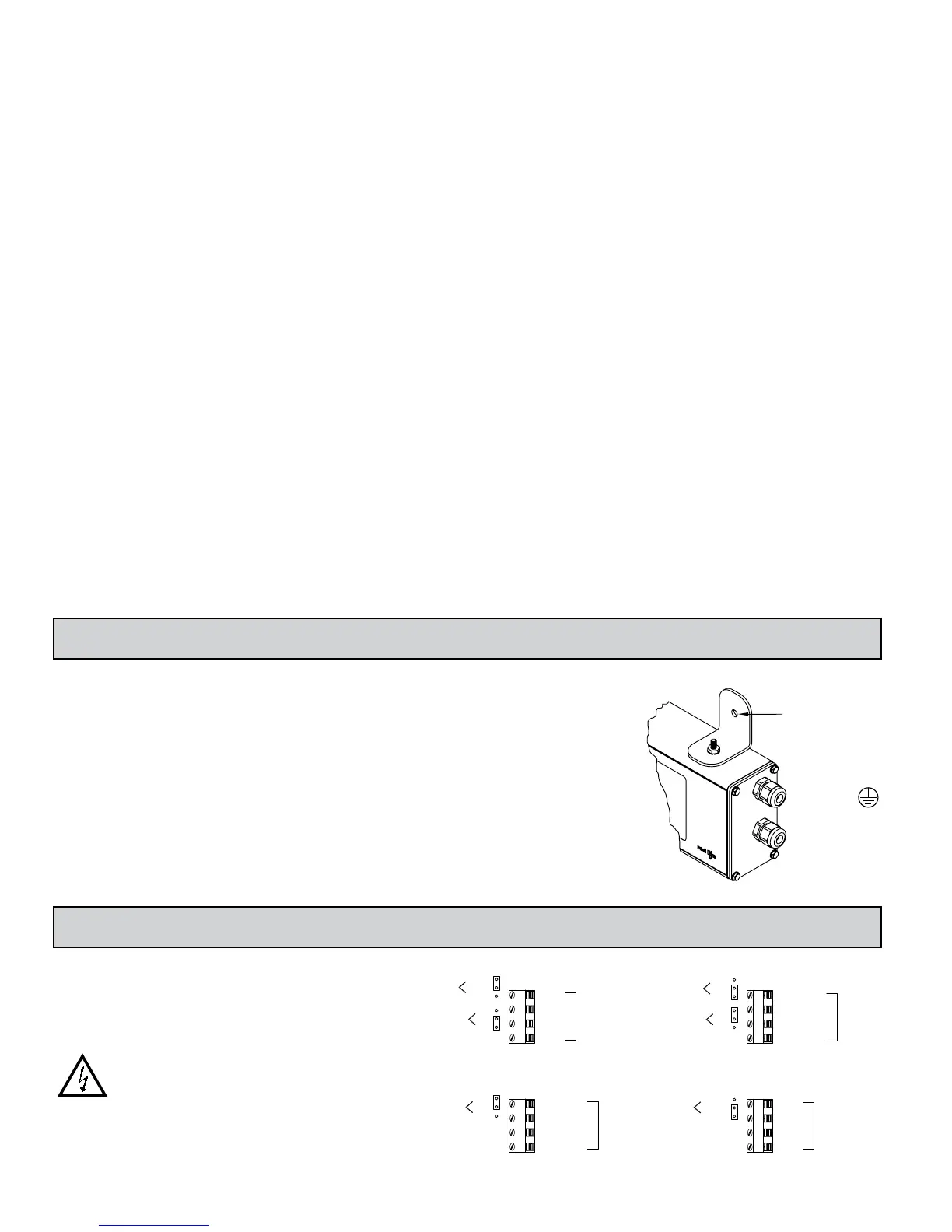
MOUNTING INSTRUCTIONS
This display is designed to be
wall mounted or suspended
from a ceiling truss or other
suitable structure capable of
supporting the LDSG.
Caution should be exercised
when hanging the display to
provide for the safety of
personnel. If hanging the LDSG,
run the suspension cables (or
chains) through the mounting
bracket holes. For wall mounting
use #10-32 size bolts.
MOUNTING HOLE (.281")
MUST BE
CONNECTED TO
TERMINAL #3 (TBA)
EXCITATION
RANGE
RANGE SELECT
2
USER 1
USER 2
USER 3
+EXC
-EXC
200mV
JUMPERS
20mV
2
+IN
3
4
-IN
1
5V
10V
3
4
TBC
TBD
USER COMM
INPUT
USER
SNK
SRC
1
LD2 JUMPERS
LD4 JUMPERS

 Loading...