EasyManua.ls Logo

red lion LD Series User Manual

red lion LD Series
20 pages
To Next Page IconTo Next Page
Page #1 background imageLoading...
Page #1 background image
1
AIR PRESSURE STABILIZATION VENT
(57.15)
2.25
X
Z
Y
DSP
PAR
F1
F1
RST
MIN
MAX
TOT
1
2
GENERAL DESCRIPTION
The Large Display is a versatile display available as a strain gage meter with
scaling, serial communications and dual relay outputs. The 5 digit displays are
available in either 2.25" or 4" high red LED digits with adjustable display
intensities. The 2.25" high models are readable up to 130 feet. The 4" high
models are readable up to 180 feet. Both versions are constructed of a Type 4X/
IP65 enclosure in light weight aluminum.
All models also come with dual Form C relay outputs and RS232 / RS485
serial communications.
The Crimson software is a Windows based program that allows configuration
of the LD meter from a PC. Crimson offers standard drop-down menu
commands, that make it easy to program the meter. The meters program can
then be saved in a PC file for future use. Crimson software can be downloaded
at www.redlion.net.
ORDERING INFORMATION
MODEL
NO.
DESCRIPTION PART NUMBER
LD 2 Preset Strain Gage Input; 2.25" High 5 Digit Red LED LD2SG5P0
LD 2 Preset Strain Gage Input; 4" High 5 Digit Red LED LD4SG5P0
LD Plug Cord Grip Plug for LD models * LDPLUG00
* Required to maintain Type 4X/IP65 specification, if end plate cord grip does not
have cable installed.
SAFETY SUMMARY
All safety regulations, local codes and instructions that appear in this and
corresponding literature, or on equipment, must be observed to ensure personal
safety and to prevent damage to either the instrument or equipment connected to
it. If equipment is used in a manner not specified by the manufacturer, the
protection provided by the equipment may be impaired.
SPECIFICATIONS
1. DISPLAY: 5 digit, 2.25" (57 mm) or 4" (101 mm) intensity adjustable Red LED
(-99999 to 99999)
2. POWER REQUIREMENTS:
AC POWER: 40 to 250 VAC 50/60 Hz, 27 VA
DC POWER: 21.6 to 250 VDC, 12 W
Isolation: 3000 Vrms for 1 min.; Power IN to all inputs and outputs
3. INPUT RANGES:
INPUT
RANGE
ACCURACY*
(18 to 28 °C)
ACCURACY*
(0 to 65 °C)
IMPEDANCE
MAX
CONTINUOUS
OVERLOAD
RESOLUTION
±24 mVDC
0.02% of
reading +3 µV
0.07% of
reading +4 µV
100 Mohm 30 V 1 µV
±240 mVDC
0.02% of
reading +30 µV
0.07% of
reading +40 µV
100 Mohm 30 V 10 µV
* After 20 minute warm-up. Accuracy is specified in two ways: Accuracy over
an 18 to 28 °C and 10 to 75% RH environment; and accuracy over a 0 to 65
°C and 0 to 85% RH (non-condensing environment). Accuracy over the 0 to
65 °C range includes the temperature coefficient effect of the meter.
4. CONNECTION TYPE: 4-wire bridge (differential)
2-wire (single-ended)
5. COMMON MODE RANGE (w.r.t. input common): 0 to +5 VDC
Rejection: 80 dB (DC to 120 Hz)
6. BRIDGE EXCITATION :
Jumper Selectable: 5 VDC @ 65 mA max., ±2%
10 VDC @ 125 mA max., ±2%
Temperature coefficient (ratio metric): 20 ppm/°C max.
7. A/D CONVERTER: 16 bit resolution
8. UPDATE RATES:
A/D conversion rate: 20 readings/sec.
Step response: 200 msec. max. to within 99% of final readout value
(digital filter and internal zero correction disabled)
700 msec. max. (digital filter disabled, internal zero correction enabled)
Display update rate: 1 to 20 updates/sec.
Setpoint output on/off delay time: 0 to 3275 sec.
MODEL LD - LARGE STRAIN GAGE DISPLAY
DIMENSIONS In inches (mm)
Bulletin No. LDSG-B
Drawing No. LP0914
Effective 06/16
Tel +1 (717) 767-6511
Fax +1 (717) 764-0839
www.redlion.net
22 (558.8)
12 (304.3)
Z (Center)
7.875 (200)26 (660.4)LD4
4 (101.6)16 (406.4)LD2
Y (Height)X (Length)
PART
NUMBER
The protective conductor terminal is bonded to conductive
parts of the equipment for safety purposes and must be
connected to an external protective earthing system.
CAUTION: Risk of Danger.
Read complete instructions
prior to installation and
operation of the unit.
CAUTION:
Hot Surface
CAUTION:
Risk of electric shock.
2.25" & 4" HIGH RED LED DIGITS
PROGRAMMABLE SCALING AND DECIMAL POINTS
PROGRAMMABLE USER INPUT
DUAL 5 AMP FORM C RELAY
ALUMINUM TYPE 4X/IP65 CASE CONSTRUCTION
RS232/RS485 SERIAL COMMUNICATIONS
CRIMSON
®
PROGRAMMING SOFTWARE
UNIVERSALLY POWERED

Other manuals for red lion LD Series

Question and Answer IconNeed help?

Do you have a question about the red lion LD Series and is the answer not in the manual?

red lion LD Series Specifications

General IconGeneral
BacklightLED
Contrast Ratio500:1
Display Size15 inch
Operating Temperature0°C to 50°C
CommunicationEthernet
ProtocolsModbus
EnclosureNEMA 4X
Viewing AngleHorizontal: 140°, Vertical: 120°
Storage Temperature-20°C to 60°C

Summary

Specifications - Core Features

Display and Power Specs

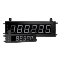
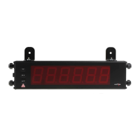
Details on LED display type, intensity, and power requirements.

Input Ranges and Excitation

Specifications for input ranges, accuracy, and bridge excitation.

Specifications - Advanced Features

User Inputs, Totalizer, Comms

Programmable inputs, totalizer functions, RS485/RS232 communications.

Environmental, Construction, Certs

Operating conditions, enclosure type, weight, and certifications.

Installation and Jumper Settings

Installation Environment and Mounting

Guidelines for location, mounting, and cleaning the unit.

Input Range Jumper Configuration

Setting jumpers for input range, excitation, and input type.

Meter Wiring Guidelines

EMC Installation and Wiring Connections

Ensuring EMI compatibility and details on terminal blocks/cord grips.

Meter Wiring Details

Power, Input, User Input Wiring

Connecting terminal blocks for power, signals, and user inputs.

Setpoint (Output) Wiring

Wiring the setpoint relays using terminal block TBB.

Serial Communications and Front Panel Overview

Serial Wiring (RS232/RS485)

Connecting for RS232 and RS485 serial communications.

Front Panel Key Operations

Key functions for display mode and programming mode operations.

Programming the Meter - Entry and Modes

Programming Modes and Tips

Understanding Full/Quick modes, programming tips, and factory settings.

Step-by-Step Programming Instructions

Guide for entering, navigating, and setting parameters.

Module 1 - Signal Input Parameters

Input Range, Decimal Point, Rounding

Configuring input range, decimal point, and display rounding.

Filter Settings and Scaling Parameters

Setting input filter and defining scaling points/style.

Module 1 - Scaling Point Value Entry

Input and Display Value Entry

Entering input and display values for scaling points.

Module 2 - User Input and Function Keys

User Inputs and Function Key Programming

Programming user inputs and front panel keys for specific functions.

Mode Lock-Out and Zero Display

Locking programming and zeroing the display value.

Display Modes and Totalizer Control

Relative/Absolute display, Hold, Zero Display, Totalizer batching.

Module 2 - Control Functions

Totalizer and Display Value Controls

Resetting, enabling totalizer, and controlling max/min displays.

Setpoint and Print Functionality

Configuring setpoints and requesting printouts.

Module 3 - Display and Program Lock-Out

Display Lock-out and Setpoint Access

Locking displays and configuring setpoint access.

Program Mode Access Control

Managing security codes and access to programming modes.

Module 4 - Secondary Function Parameters

Capture Delay, Update Rate, Auto-Zero

Configuring capture delays, display update, and auto-zero tracking.

Display Offset and Backlight Settings

Setting display offset value and unit label backlight.

Module 5 - Totalizer Parameters

Totalizer Decimal Point and Time Base

Setting totalizer decimal point and time base for accumulation.

Scale Factor, Low Cut Value, and Batching

Configuring totalizer scale, low cut value, and batch operations.

Module 6 - Setpoint (Alarm) Parameters

Setpoint Selection, Action, and Value

Choosing setpoints, defining actions, and setting alarm values.

Hysteresis, Time Delays, and Output Logic

Configuring hysteresis, delays, and output logic for alarms.

Module 6 - Setpoint Advanced Settings

Setpoint Value, Assignment, and Hysteresis

Setting alarm values, sources, and hysteresis.

Time Delays, Logic, Reset Actions, Alternates

Configuring delays, logic, resets, and alternate setpoints.

Module 7 - Serial Communications

Baud Rate, Data, Parity, Address

Configuring serial settings: baud, data bits, parity, and meter address.

Print Options and Values

Selecting print format and which values to include in prints.

Sending Commands and Data

Command Structure and Data Transmission

Details on command format, numeric data, and response modes.

Transmission Formats

Description of full field and abbreviated transmissions.

Serial Commands for LD Software

Control Status Register (CSR)

Controlling setpoint outputs and reading their status via CSR.

Command Response Time

Understanding timing for commands and data transmission.

Communication Format and Service Operations

Interface States and Character Framing

Voltage levels and data framing for serial communication.

Module 9 - Factory Service Operations

Adjusting display intensity and restoring factory settings.

Calibration Procedure

Steps for performing input calibration of the meter.

Related product manuals