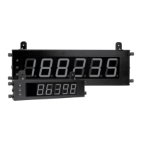
77
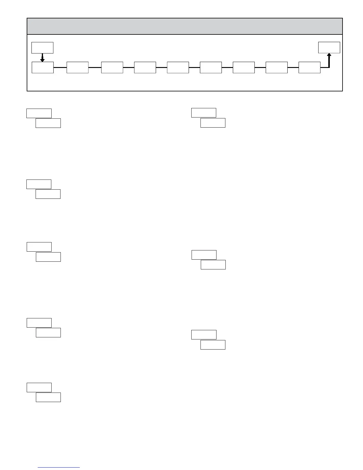
5.1 Module 1 - sIgnal Input paraMeters ()
1-INP
Display
Decimal Point
dECPt
Input
Range
rAN6E
Display
Rounding
round
Scaling
Style
StYLEFILtr
Filter
Setting
bANd
Filter
Band
Scaling
Points
PtS
Display x
Value
dSP
Input x
Value
INP
PAR
Pro
PARAMETER MENU
0.02u
INPUT RANGE
Select the input range that corresponds to the external signal. This selection
should be high enough to avoid input signal overload but low enough for the
desired input resolution. This selection and the position of the Input Range
Jumper must match.
RANGE
RESOLUTION
SELECTION
±24 mV
0.2
±240 mV
0
DISPLAY DECIMAL POINT
Select the decimal point location for the Input, MAX and MIN displays. (The
TOT display decimal point is a separate parameter.) This selection also affects
u, and 2 parameters and setpoint values.
u
DISPLAY ROUNDING
Rounding selections other than one, cause the Input Display to ‘round’ to the
nearest rounding increment selected (ie. rounding of ‘5’ causes 122 to round to
120 and 123 to round to 125). Rounding starts at the least significant digit of
the Input Display. Remaining parameter entries (scaling point values, setpoint
values, etc.) are not automatically adjusted to this display rounding selection.
.0
FILTER SETTING
The input filter setting is a time constant expressed in tenths of a second. The
filter settles to 99% of the final display value within approximately 3 time
constants. This is an Adaptive Digital Filter which is designed to steady the
Input Display reading. A value of ‘0’ disables filtering.
0.0 to 2.0 seconds
0
FILTER BAND
The digital filter will adapt to variations in the input signal. When the
variation exceeds the input filter band value, the digital filter disengages. When
the variation becomes less than the band value, the filter engages again. This
allows for a stable readout, but permits the display to settle rapidly after a large
process change. The value of the band is in display units. A band setting of ‘0’
keeps the digital filter permanently engaged.
0.0 to 2.0 display units
2
SCALING POINTS
Linear - Scaling Points (2)
For linear processes, only 2 scaling points are necessary. It is recommended
that the 2 scaling points be at opposite ends of the input signal being applied.
The points do not have to be the signal limits. Display scaling will be linear
between and continue past the entered points up to the limits of the Input Signal
Jumper position. Each scaling point has a coordinate-pair of Input Value ()
and an associated desired Display Value ().
Nonlinear - Scaling Points (Greater than 2)
For non-linear processes, up to 16 scaling points may be used to provide a
piece-wise linear approximation. (The greater the number of scaling points
used, the greater the conformity accuracy.) The Input Display will be linear
between scaling points that are sequential in program order. Each scaling point
has a coordinate-pair of Input Value () and an associated desired Display
Value (). Data from tables or equations, or empirical data could be used to
derive the required number of segments and data values for the coordinate pairs.
2 to
SCALING STYLE
If Input Values and corresponding Display Values are known, the Key-in
() scaling style can be used. This allows scaling without the presence or
changing of the input signal. If Input Values have to be derived from the actual
input signal source or simulator, the Apply () scaling style must be used.
After using the Apply () scaling style, this parameter will default back to
but the scaling values will be shown from the previous applied method.
key-in data
apply signal
0.00
INPUT VALUE FOR SCALING POINT 1
For Key-in (), enter the known first Input Value by using the arrow keys.
The Input Range selection sets up the decimal location for the Input Value. With
0.02 V Input Range, 0 mV would be entered as 0.000. For Apply (), apply
the input signal to the meter, adjust the signal source externally until the desired
Input Value appears. In either method, press the PAR key to enter the value
being displayed.
to
Note: style - Pressing the RST key will advance the display to the next
scaling display point without storing the input value.

 Loading...