18
CYCLE TIME
to 2 seconds
This cycle time functions like the O1 Output Cycle Time but allows
independent cycle time for cooling. A setting of zero will keep output O2 off.
RELATIVE GAIN
to 1
This defines the gain of the cooling relative to the heating. It is generally set
to balance the effects of cooling to that of heating. This is illustrated in the Heat/
Cool Relative Gain Figures. A value of 0.0 places the cooling output into On/
Off Control.
2
DEADBAND/OVERLAP
to
This defines the overlap area in which both heating and cooling are active
(negative value) or the deadband area between the bands (positive value). If a
heat/cool overlap is specified, the percent output power is the sum of the heat
power (O1) and the cool power (O2). If Relative Gain is zero, the cooling
output operates in the On/Off Control Mode, with the On/Off Control
Hysteresis in Output Module 2 becoming the cooling output hysteresis.
The function of Deadband is illustrated in the Control Mode Explanations. For
most applications, set this parameter to 0.0 prior to starting Auto-Tune. After
the completion of Auto-Tune, this parameter may be changed.
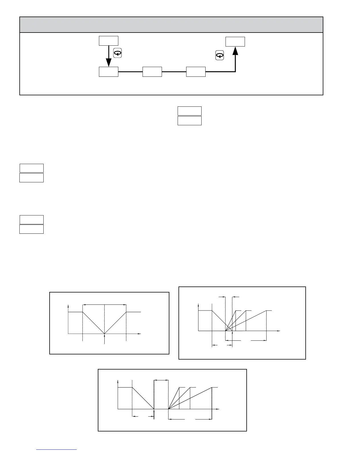
7.5 module 5 - Cooling (SeCondAry) pArAmeterS (5-O2)
CYC2 db-2gAN2
COOLING
CYCLE
COOLING
RELATIVE
HEAT/COOL
DEADBAND/
5-O2
CNFP
OVERLAPTIME GAIN
PARAMETER MENU
To enable Cooling in Heat/Cool applications, the Alarm 2 Action must first
be set for Cooling. (For P16 Controllers, the cooling output is sometimes
referred to as secondary output.) When set to cooling, the output no longer
operates as an alarm but operates as a cooling output. The O2 terminals are the
same as A2, however a separate O2 annunciator indicates Cooling Operation.
Cooling output power ranges from -100% (full cooling) to 0% (no cooling,
unless a heat/cool overlap is used). The Power Limits in Output Module 2-OP
also limit the cooling power. In applications requiring only a Cooling output,
the main 01 output should be used.
2
2
1
2
TEMPERATURE
COOLHEAT
SETPOINT
-100%
O2
+100%
O1
2X PROPORTIONAL
BAND
%
OUTPUT
POWER
O1
+100%
SETPOINT
DEADBAND
NEGATIVE VALUE
COOL
RELATIVE GAIN = .5
.512
RELATIVE GAIN
O2
-100%
TEMPERATURE
HEAT
%
OUTPUT
POWER
TEMPERATURE
HEAT
SETPOINT
-100%
O2
+100%
O1
DEADBAND
POSITIVE VALUE
RELATIVE GAIN
21 .5
RELATIVE GAIN = .5
COOL
%
OUTPUT
POWER
HEAT/COOL RELATIVE GAIN FIGURES
Heat/Cool Deadband = 0
Heat/Cool Deadband < 0
Heat/Cool Deadband > 0
 Loading...

