6
3.0 Wiring the Controller
WIRING CONNECTIONS
All wiring connections are made to the rear screw terminals. When wiring the
controller, use the numbers on the label and those embossed on the back of the
case, to identify the position number with the proper function.
All conductors should meet voltage and current ratings for each terminal.
Also, cabling should conform to appropriate standards of good installation, local
codes and regulations. It is recommended that power (AC or DC) supplied to the
controller be protected by a fuse or circuit breaker. Strip the wire, leaving
approximately 1/4" (6 mm) bare wire exposed (stranded wires should be tinned
with solder). Insert the wire under the clamping washer and tighten the screw
until the wire is clamped tightly.
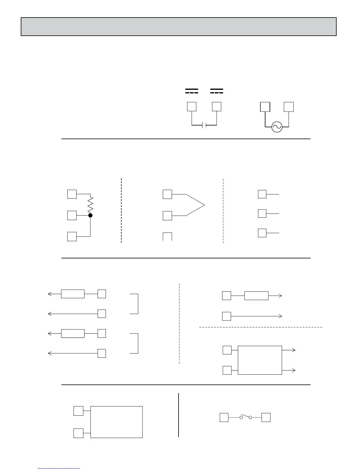
CONTROLLER POWER CONNECTIONS
For best results, the power should be relatively “clean” and within
the specified limits. Drawing power from heavily loaded circuits or
from circuits that also power loads that cycle on and off should be
avoided. It is recommended that power supplied to the controller be
protected by a fuse or circuit breaker.
DC-DC+
1211
+-
ACAC
1211
INPUT CONNECTIONS
For two wire RTDs, install a copper sense lead of the same gauge and length
as the RTD leads. Attach one end of the wire at the probe and the other end to
input common terminal. Complete lead wire compensation is obtained. This is
the preferred method. If a sense wire is not used, then use a jumper. A
temperature offset error will exist. The error may be compensated by
programming a temperature offset.
RTD 10
TC+9
OMM 8
TC+
9
OMM 8
TC+
TC-
10V
10
9
COMM
8
DC+ VOLTAGE
DC-
DC+ CURREN
CONTROL AND ALARM OUTPUT CONNECTIONS
VDC
VAC
RTD and Resistance Thermocouple and Millivolt
Voltage and Current
4
3
COMM.
5 COMM.
N.O.
LOAD
C/DC
R
R
C/DC
A1/O1*
7
6
AC/DC
POWER
LOAD
(-) O1
7
6
AC POWE
SSR
(-) O1
POWER
UNIT
-
AC
AC
Alarm Models Main Control Relay Models
Main Control Logic/SSR Models
ANALOG DC OUTPUT CONNECTIONS
USER INPUT CONNECTIONS
81
T
*A1 becomes main control O1, if selected for
heating in the analog out models.
7
6
CONTROLLER,
+ V/I
RECORDER
- V/I
 Loading...

