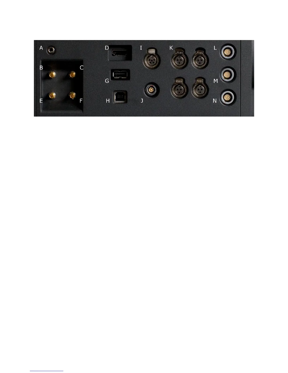
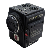
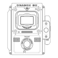
A Headphone B Program HD-SDI (A) C Program HD-SDI (B)
D HDMI Out E Preview HD-SDI F Video Genlock
G USB-2 (peripheral) H USB-2 (computer) I Audio Monitor
J Timecode K Audio Ch 1 – 4 (1-2 Upper Left - Right, 3-4 Lower Left - Right)
L RED-EVF M RED-LCD N Aux / RS232
The right side of the camera contains all the video, audio and time code inputs and outputs.
From top left to bottom right, these comprise a 3.5mm stereo headphone jack, and four DIN
1.0/2.3 video connectors that support Program HD-SDI, Preview HD-SDI and Video Genlock.
Next is an HDMI output, a USB-2 “master” port for USB peripheral devices, a USB-2 “slave”
port to connect the camera to another camera or computer based controller, a 5-pin mini-XLR
audio output, a 5-pin timecode input/output and four three-pin mini-XLR audio inputs. Finally
there are two 16-pin push lock LEMO connectors that provide video, communications and
power for a RED-EVF and RED-LCD, and a 10-pin push lock LEMO connector supporting the
Aux/RS232 port that can interface to a variety of B4 lenses and lens motor control devices.
One 6-inch length DIN 1.0 / 2.3 to BNC video adaptor cable and one 9-inch length 3 pin mini-
XLR to mini-XLR cable plus a mini-XLR to full size XLR adaptor are provided with the camera.
Additional video and audio adaptor cables may be ordered online at www.red.com/store
Note: Cameras shipped prior to Sept 15th 2008, may have an earlier revision of the audio
board and no S4/i pins installed in the P/L mount. Contact RED customer service about
appropriate audio cables to use with these systems, and hardware upgrade options.