8
5 INSTALLATION
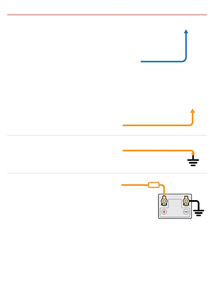
5.2 BLUE wire—Ignition Control
The BLUE wire should be connected to the vehicle’s
ignition or, if required, a dedicated ON/OFF switch.
When connected in this way, the power supply will only
run the connected loads when the vehicle ignition is ON,
guaranteeing that the power supply will not drain the
start battery.
Vehicle
Ignition
BLUE
Wire
5.3 ORANGE wire—Output Voltage Select
The ORANGE wire is used to select the output voltage.
This is achieved by connecting in the following way:
PROFILE A
For 12.0V output on the DPS1225/DPS1240 or 24.0V
output on the DPS2410/DPS2420, leave the ORANGE
wire disconnected.
Not
Connected
ORANGE
Wire
ORANGE
Wire
Ground
Fuse
AUXILIARY
BATTERY
ORANGE
Wire
PROFILE B
For 13.7V output on the DPS1225/DPS1240 or 27.4V
output on the DPS2410/DPS2420, connect the ORANGE
wire to Common Ground.
OR
OR
Not
Connected
ORANGE
Wire
ORANGE
Wire
Ground
Fuse
AUXILIARY
BATTERY
ORANGE
Wire
PROFILE C
For 14.5V output on the DPS1225/DPS1240 or 29.0V
output on the DPS2410/DPS2420, connect the ORANGE
wire to the RED wire (Input source positive).
OR
OR
Not
Connected
ORANGE
Wire
ORANGE
Wire
Ground
Fuse
AUXILIARY
BATTERY
ORANGE
Wire